
Ground-fault resistance measurement circuit and ground-fault detection circuit

a ground-fault resistance and measurement circuit technology, applied in testing circuits, instruments, electric devices, etc., can solve the problems of difficult to heighten the frequency of alternating voltage vx, complex circuit configuration, and resistance drops between the charge section and the body, so as to improve the measurement accuracy of ground-fault resistance easily

Inactive Publication Date: 2009-07-14
PANASONIC CORP +1
View PDF4 Cites 42 Cited by
  • Summary
  • Abstract
  • Description
  • Claims
  • Application Information

AI Technical Summary

Benefits of technology

"The present invention provides a ground-fault resistance measurement circuit that can improve the accuracy of measuring ground-fault resistance without using a constant-current circuit. The circuit includes a capacitor, a switch, a charging unit, a voltage measurement section, a discharge control section, and a calculation section. The charging unit charges the capacitor using a set voltage, and the discharge control section closes the switch after charging. The voltage measurement section measures the charging voltage, which changes over time based on the capacitor's capacitance and the ground-fault resistance. The calculation section calculates the resistance value of the ground-fault resistance using the measured charging voltage and the time constant. This results in a more accurate measurement of ground-fault resistance."

Problems solved by technology

If a ground fault is caused, the resistance drops between the charge section and the body.
A ground fault occurs, for example, when the covering of a cable is broken and it comes into contact with the vehicle body.
However, this presents a disadvantage in that a constant-current circuit like the constant-current source 109 makes the circuit configuration complicated.
This is undesirable.
This makes it difficult to heighten the alternating voltage Vx's frequency.
Accordingly, there is a disadvantage in that it is difficult to improve the measurement precision of the ground-fault resistance value Rx by heightening the alternating voltage Vx's frequency and lowering the capacitor 124's impedance.
Therefore, a disadvantage arises in that it is difficult to improve the measurement precision of the ground-fault resistance value Rx by increasing the capacitor 124's capacitance and lowering the capacitor 124's impedance.

Method used


Image

  • Ground-fault resistance measurement circuit and ground-fault detection circuit
  • Ground-fault resistance measurement circuit and ground-fault detection circuit
  • Ground-fault resistance measurement circuit and ground-fault detection circuit

Examples


Embodiment Construction

[0033]Hereinafter, a ground-fault resistance measurement circuit according to an embodiment of the present invention will be described with reference to the attached drawings. In each figure, component elements are identical with each other if given the same reference characters and numerals. Thus, their description is omitted.

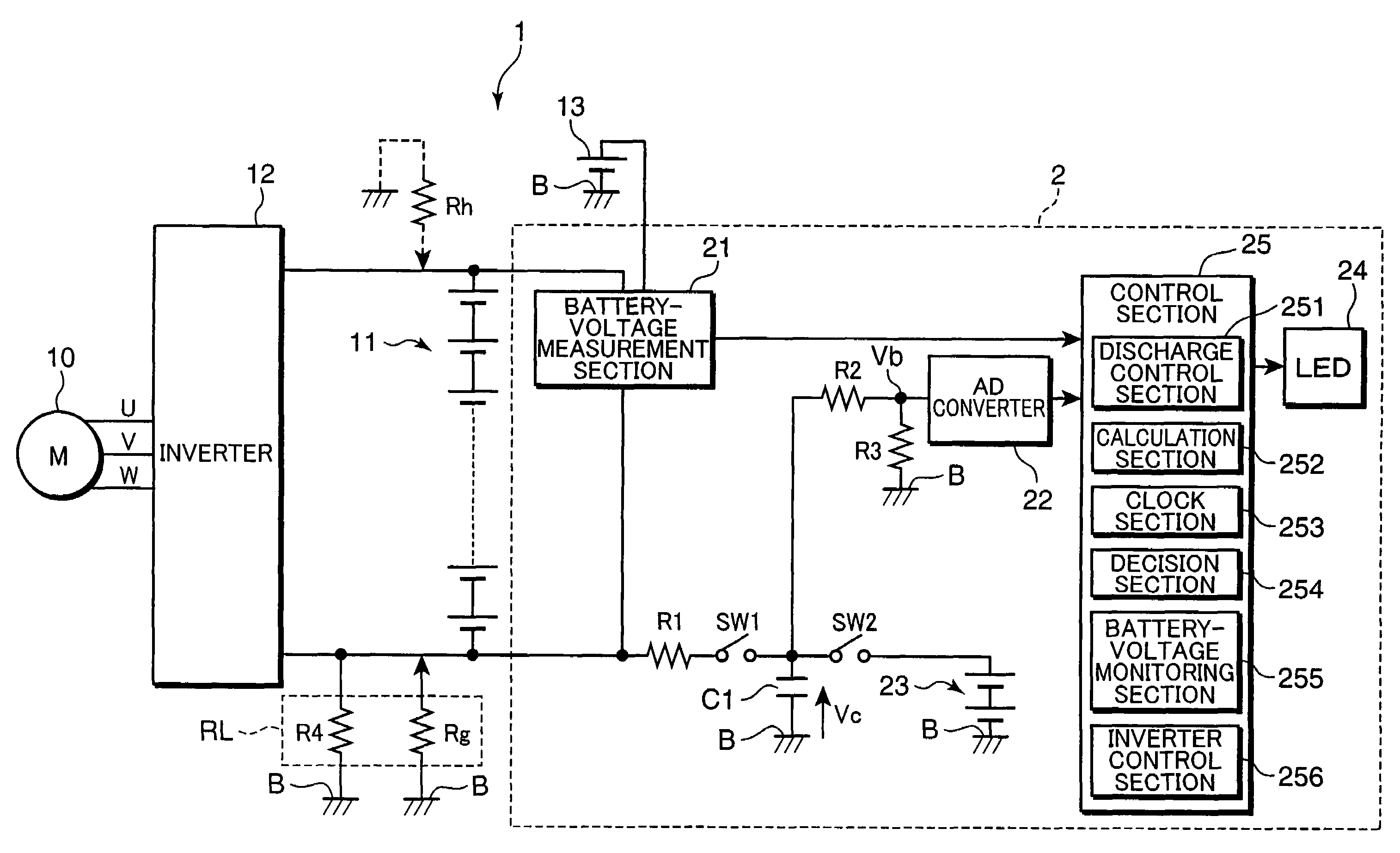
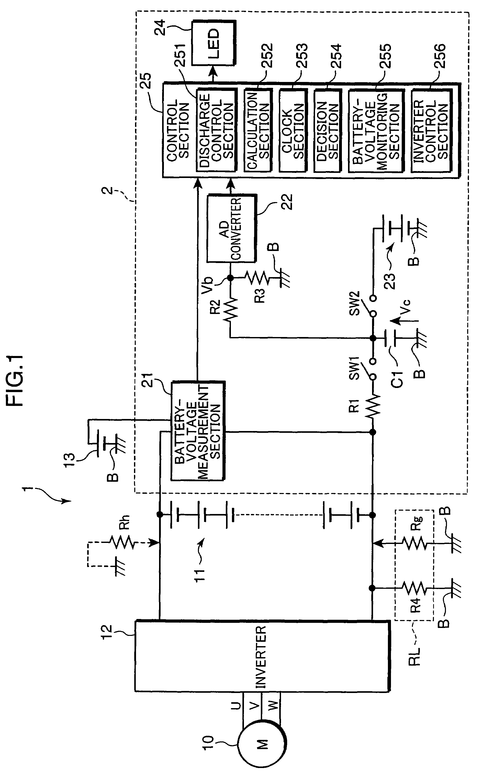
[0034]FIG. 1 is a circuit diagram, showing an example of the configuration of a ground-fault detection circuit provided with the ground-fault resistance measurement circuit according to the embodiment of the present invention. A ground-fault detection circuit 2 shown in FIG. 1 is mounted, for example, in a vehicle 1 such as an electric automobile, like a hybrid car or a fuel-battery vehicle. The ground-fault detection circuit 2 measures a resistance value RL of a ground-fault resistance RL which corresponds to a resistance between the charge section and a vehicle body B. Based on this resistance value RL, it detects a ground fault being generated.

[0035]The veh...


PUM


Abstract

There is a ground-fault resistance measurement circuit which measures a ground-fault resistance between a conductive frame body of electrical equipment and a charge section insulated from the frame body. This ground-fault resistance measurement circuit includes: a capacitor which is connected between the charge section and the frame body; a switch which opens and closes a connection path between the charge section and the capacitor; a charging unit which charges the capacitor to a predetermined voltage; a voltage measurement section which measures a charging voltage of the capacitor; a discharge control section which connects the capacitor and the charge section after the capacitor is charged, and discharges the capacitor; and a calculation section which calculates a resistance between the charge section and the frame body, based on a change in the charging voltage of the capacitor.

Description

BACKGROUND OF THE INVENTION[0001]1. Field of the Invention[0002]The present invention relates to a ground-fault resistance measurement circuit which measures a ground-fault resistance between a charge section insulated from a conductive frame body of electrical equipment and the frame body. It also relates to a ground-fault detection circuit provided with this.[0003]2. Description of the Background Art[0004]In recent years, hybrid cars have been widely popular which have both an engine and an electric motor. Along with this, electric cars, such as a fuel-battery vehicle, have also been put to more use. Such a vehicle which has an electric motor as its power source includes a high-voltage power source for driving the motor. In order to prevent a user from touching the vehicle's body and getting an electric shock, a charge section connected to the part of the high-voltage power source is insulated from the body. In this specification, the “charge section” means a “live part” defined i...

Claims


Application Information

Patent Timeline
Patent Type & Authority Patents(United States)
IPC IPC(8): G01R31/08
CPCB60L3/0023B60L3/0046B60L3/0053B60L3/0069G01R27/18B60L2200/26G01R31/025Y02T90/34B60L2250/30G01R31/52Y02T90/40
Inventor MORIMOTO, NAOHISA
Owner PANASONIC CORP
Learn More