Molding device with height-adjustable base for molding thermoplastic containers of various heights

a molding device and height-adjustable technology, applied in the direction of dough shaping, manufacturing tools, applications, etc., can solve the problems of reducing the production efficiency of thermoplastic containers, so as to achieve quick and economical adjustment

Inactive Publication Date: 2009-07-21
SIDEL PARTICIPATIONS SAS
View PDF7 Cites 3 Cited by
  • Summary
  • Abstract
  • Description
  • Claims
  • Application Information

AI Technical Summary

Benefits of technology

[0014]It is an object of the invention to remedy the aforementioned disadvantages by proposing an improved structure that allows for quick and economical adjustment of the axial position of the mold base in relation to the height of the molding cavity.
[0017]Because recourse is had to two screw threads of opposite hand, all the stresses to which the mold base is subjected are borne on the threads, and therefore over a large area, in other words, at a reduced pressure between the contacting parts, and therefore a lower wear rate. In addition, there are no parts rotating inside a bearing, thus eliminating friction and wear. There is no rotary contact between a transverse end of the threaded rod and the mold base, thus setting aside any possibility of wearing or deformation of this mold base. Finally, since the mold base can move axially only, there is no problem with indexing the angular position with respect to the mold.

Problems solved by technology

These adjustments, however they are made, prove to be lengthy, restrictive and, ultimately, expensive.
The disadvantage with this solution lies in the fact that all the stresses that oppose the movement of the mold are borne at the interface between the rotary nut and the bearing: this results in wearing of the rubbing parts and a risk of the nut being torn out of the bearing.
However, such an arrangement would in turn have a disadvantage which would be the wearing of the mold base in contact with the rotary transverse face of the threaded rod, or even possible deformation of the mold base resting against said small cross-section transverse face of the threaded rod.

Method used


Image

  • Molding device with height-adjustable base for molding thermoplastic containers of various heights
  • Molding device with height-adjustable base for molding thermoplastic containers of various heights
  • Molding device with height-adjustable base for molding thermoplastic containers of various heights

Examples


Embodiment Construction

[0024]In the remainder of the description, the same numerical references as were used in FIGS. 1A and 1B will be kept for denoting components which are similar.

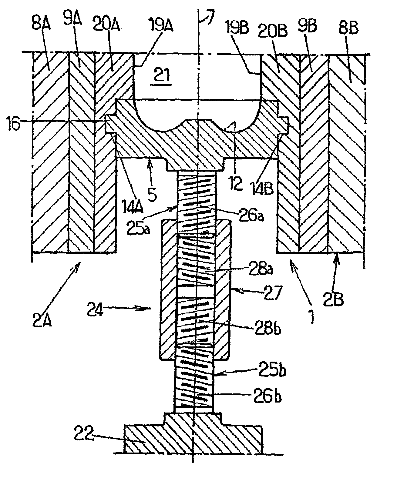
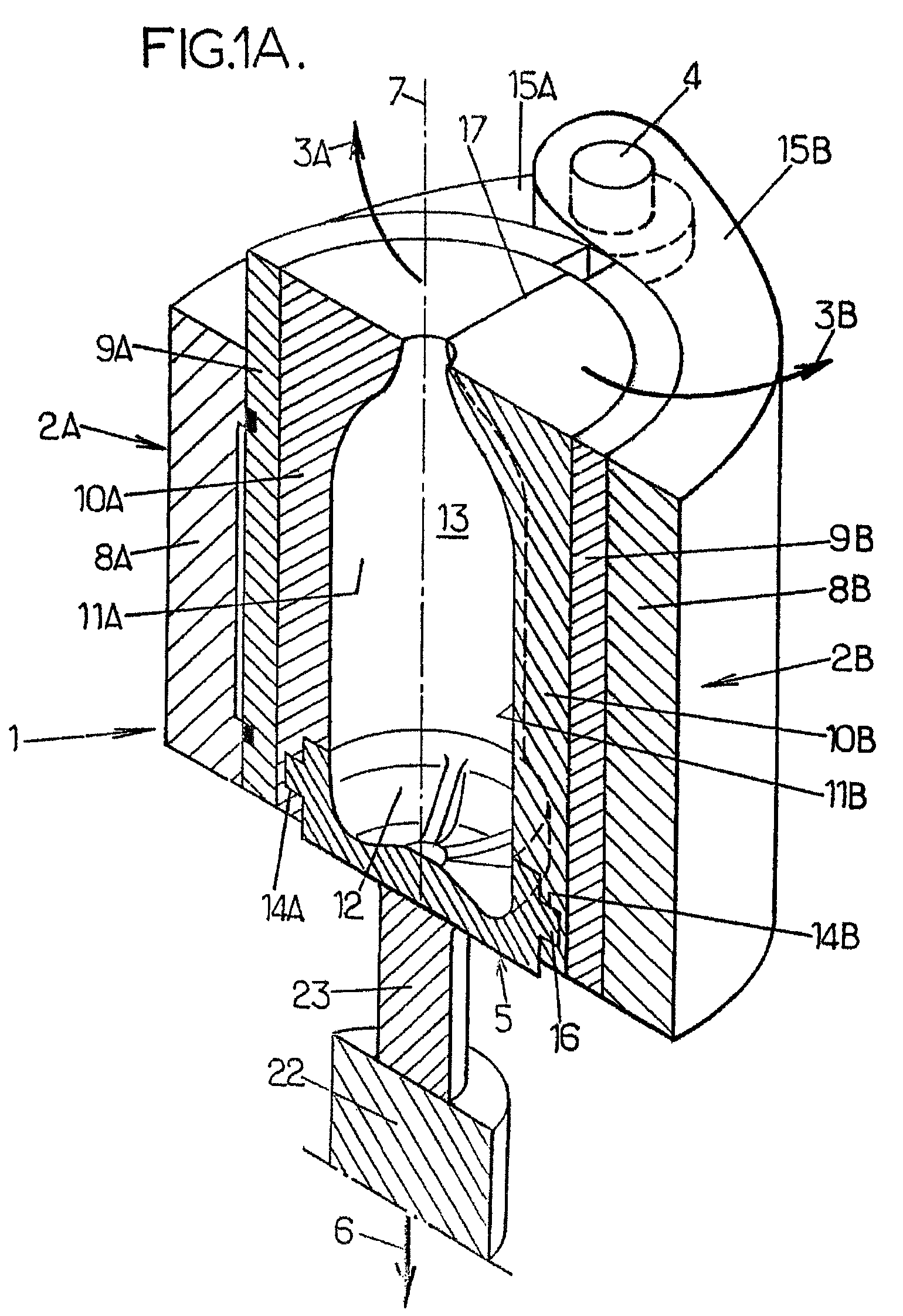
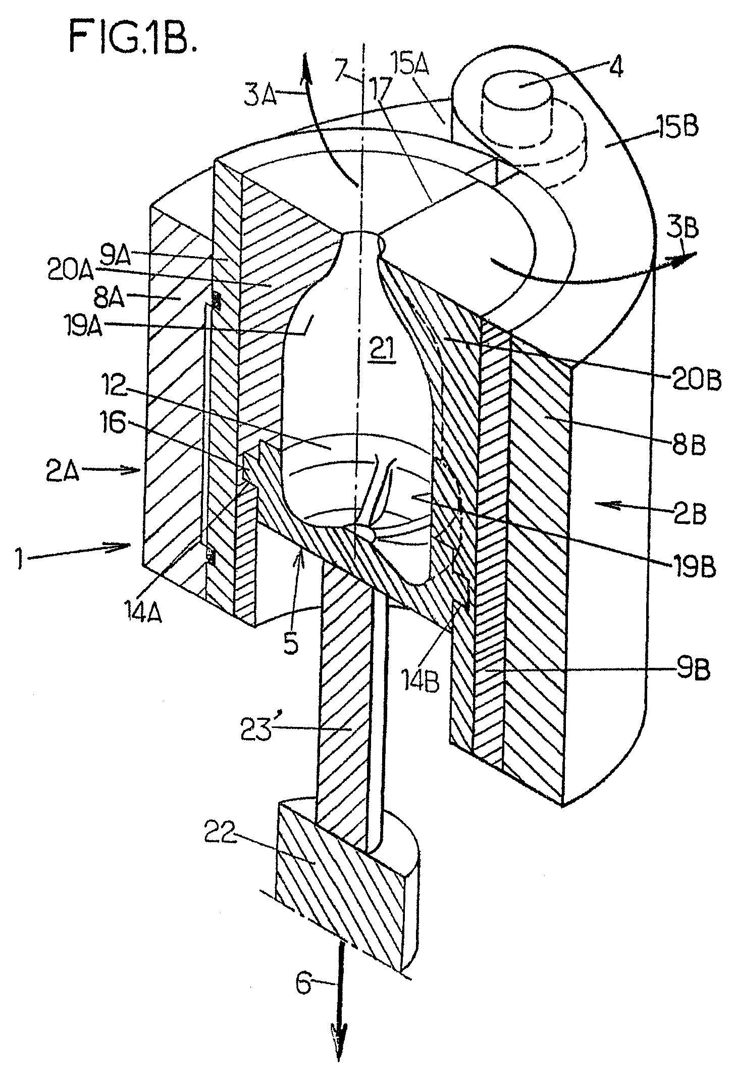
[0025]According to the object of the invention, provision is made for the rigid connection 23, 23′ illustrated in FIGS. 1A and 1B between the mold base 5 and mold base support 22 to be replaced with variable-height spacer means 24 that can be adjusted in relation to the height of the molding cavity. Thus, the mold base 5 can be positioned axially in relation to the height of the molding cavity without changing the structure and / or the position of the mold base support 22 and / or of the movement means functionally associated with it.

[0026]The spacer means 24, of a purely mechanical type, in the form of threaded means so that their structure is simple and inexpensive to manufacture, to fit and to maintain, consist, according to the invention, of threaded means with two screw threads of opposite hand, secured to the mold base 5 a...


PUM

PropertyMeasurementUnit
pressureaaaaaaaaaa
heightaaaaaaaaaa
temperatureaaaaaaaaaa

Abstract

The invention concerns a molding device for making by blow molding or stretch blow molding thermoplastic containers capable of having different heights, comprising a module (1) with two mutually mobile half-molds (2A, 2B) and an axially mobile mold base (5); the mold base is supported by a support (22) with which are associated in operation means for axial displacement; the mold base, and its support (22) are secured by spacing means (24) with adjustable variable heights relative to the height of the molding cavity and provided in the form of threaded means with reverse-pitch double threading; the mold base can thus be positioned axially relative to the height of the molding cavity without modifying the support (22) and / or the displacement means which are operatively associated with it.

Description

CROSS REFERENCE TO RELATED APPLICATIONS[0001]This application is a National Stage of International Application No. PCT / FR2006 / 000680, filed on Mar. 29, 2006, claiming priority based on French Patent Application No. 05 03240, filed Apr. 1, 2005, the contents of all of which are incorporated herein by reference in their entirety.FIELD OF THE INVENTION[0002]The present invention relates in general to the field of molding devices for manufacturing containers, particularly bottles, made of a thermoplastic such as PET by blow molding or stretch-blow molding, and it relates more particularly to improvements made to those of these molding devices that are designed to manufacture such containers, particularly such bottles, which are liable to have different heights, said molding devices comprising at least one mold which comprises two mold halves able to move relative to one another, particularly by rotation about a fixed common axle, and a mold base able to move relative to the two mold hal...

Claims


Application Information

Patent Timeline
Patent Type & Authority Patents(United States)
IPC IPC(8): B29C49/48
CPCB29C49/48B29C33/26B29C49/06B29C49/12B29L2031/7158B29C2049/4858B29C2049/4892B29K2067/00B29C2949/0715B29C2049/7831
Inventor DANNEBEY, LAURENTCANCHEL, ERICMICHELET, MARC
Owner SIDEL PARTICIPATIONS SAS
Why Eureka
Try Eureka