
Remote testing and monitoring to a cell site in a cellular communications network

Inactive Publication Date: 2009-07-28
AT&T INTPROP I L P
View PDF30 Cites 3 Cited by
  • Summary
  • Abstract
  • Description
  • Claims
  • Application Information

AI Technical Summary

Benefits of technology

[0013]To provide a system that improves productivity for network personnel by eliminating the guesswork in finding and isolating network problems, thus reducing unnecessary dispatch of technicians and reducing the mean time to repair.
[0014]To provide a system that improves productivity for a network management center by allowing technicians to instantly focus on resolving network problems rather than deciphering the network configuration.
[0015]To provide a system that reduces overtime call outs by enabling the network management center to remotely perform network testing and monitoring.
[0016]To provide a system that reduces the number of network outages by predicting, identifying and fixing network problems before they occur thereby improving customer satisfaction.
[0017]To provide a system and method that improves network quality by providing a remote, non-intrusive method of identifying and isolating intermittent problems.

Problems solved by technology

As the number of providers increases, sources of potential problems grows requiring effective, efficient trouble isolation for problem resolution.
While the reliability of wireless communications networks has increased, often, cell sites stop working.
Determining where the problems reside is challenging because communications networks include numerous components, such as, cell site equipment, central office equipment, and facilities, all which can be provided by different service providers.
Thus, isolating a problem is a long arduous process.
In the current environment, historical performance data of the transport link to the cell site can be provided, however, real time information cannot be provided.
Thus, a technician may arrive at the trouble location only to find that no trouble exists because, for instance, the trouble became clear in the time it took for the technician to arrive, the problem was not isolated to the correct piece of equipment, or the facility works properly from the technician's location towards the central office and the problem exists in a another portion of the network.
One call could involve as many as forty different carriers, making coordination between carriers a time consuming and challenging task.
Customer satisfaction suffers when technicians or network management center personnel cannot correctly identify the problem or when the problem cannot be timely resolved due to coordination problems among the various suppliers.
Customer satisfaction also suffers when the problem “came clear” since the customer may not be satisfied that the problem will not occur again.
Solving problems is exacerbated when a cellular network contains thousands of cell sites, each of which could at some point have trouble requiring technician dispatch to resolve.
Currently, central office or network management center personnel cannot remotely test the transport link in real time all the way to the cell site.
Most failures in a cellular network occur between the transport links connecting the cell site to the switch, where real time remote testing is unavailable.
Thus, no effective real time system or method exists for remote testing or performance monitoring of the transport links connecting cellular sites to a switch.
If the location where the trouble occurred cannot be identified, repairing the problem is more challenging.
Resource and technological constraints currently prevent any effective proactive, real time circuit monitoring and maintenance.
As the cellular transport network becomes larger and more complex, insuring transport link quality becomes a greater challenge.
Without the capability of robust remote testing, monitoring and analytical systems, the network is subject to less than optimal transport link quality, a greater number of field technicians are needed to handle transport link problems, and transport link maintenance suffers as a result of field technicians working priority outages.
Due to bandwidth limitations and limitations in the existing CSU, network performance monitoring has not reached the cell site.

Method used


Image

  • Remote testing and monitoring to a cell site in a cellular communications network
  • Remote testing and monitoring to a cell site in a cellular communications network
  • Remote testing and monitoring to a cell site in a cellular communications network

Examples


Embodiment Construction

[0024]Reference will now be made in detail to preferred embodiments of the invention, examples of which are illustrated in the accompanying drawings.

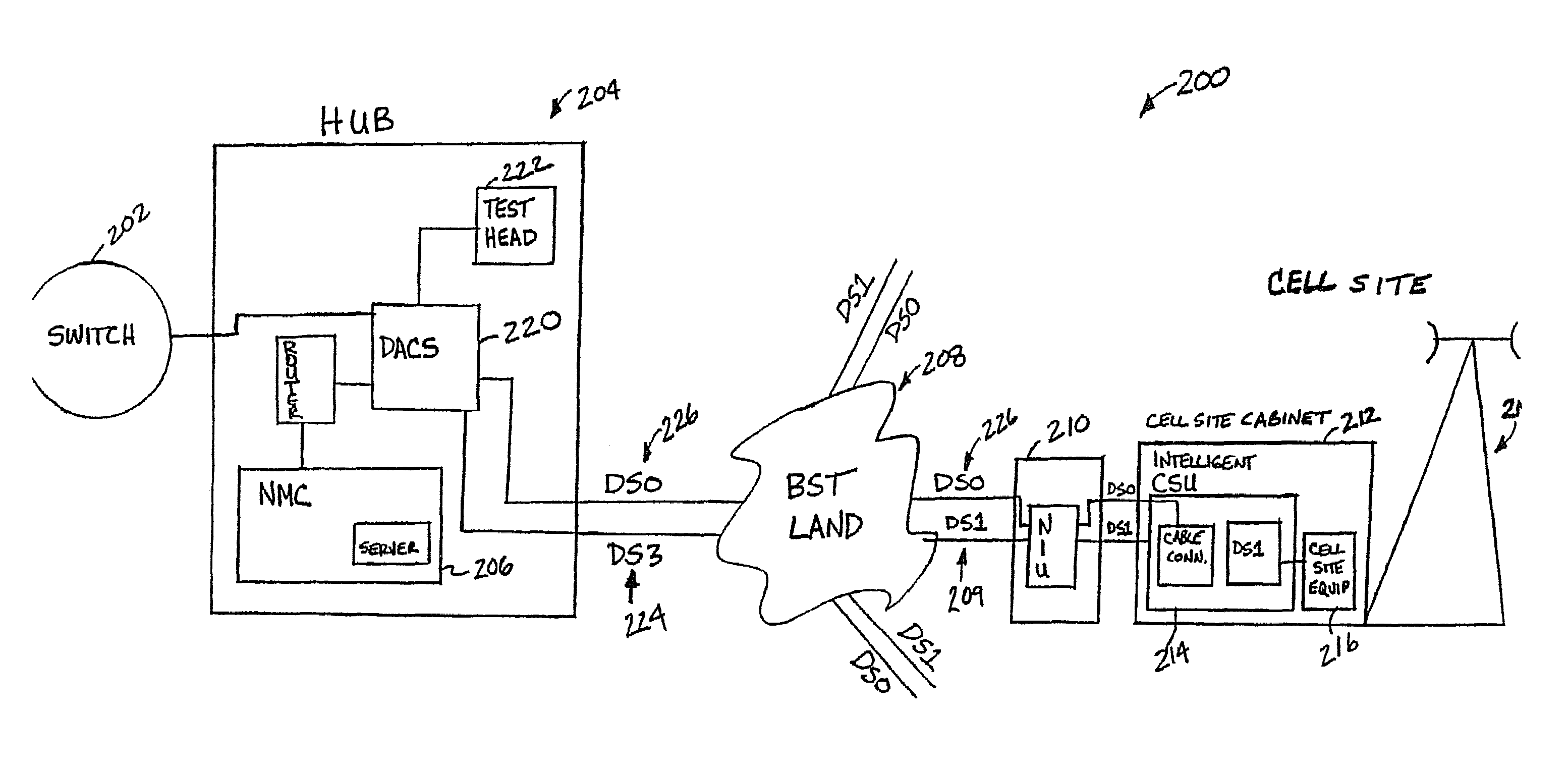
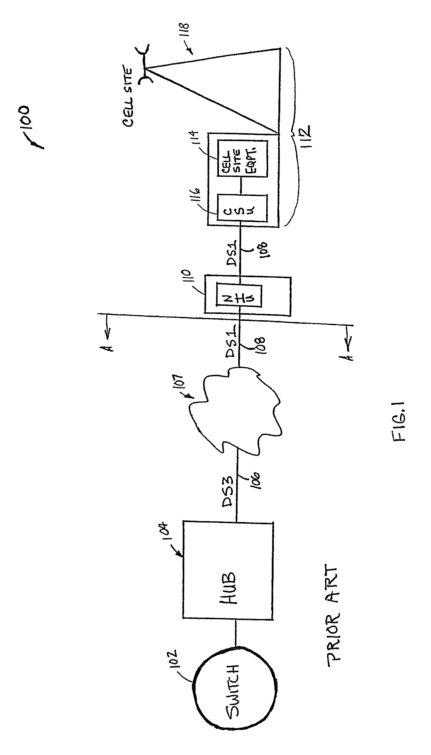
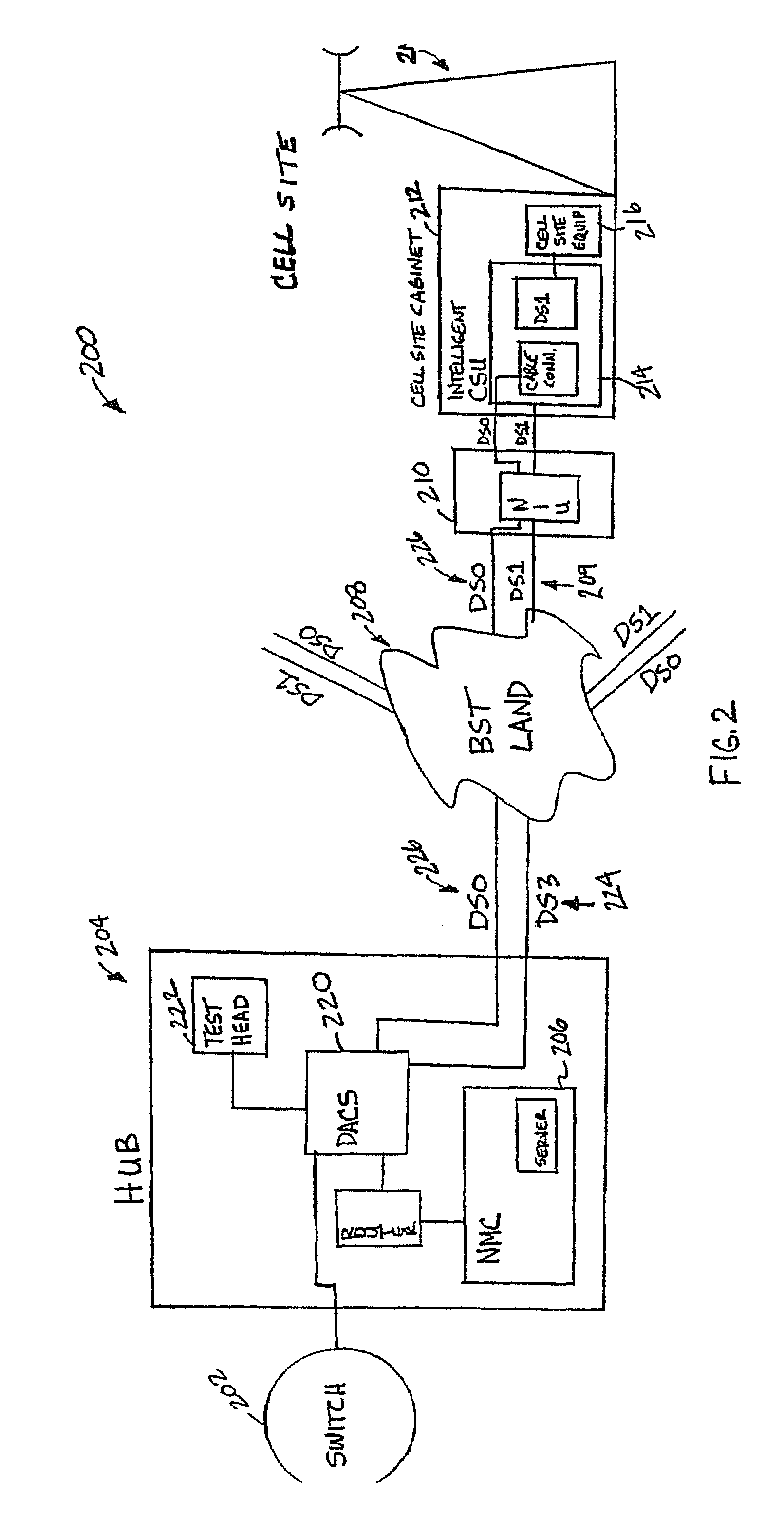
[0025]FIG. 1 shows a traditional cellular communications network 100. The cellular communications network 100 includes switches 102 that communicates with other switches located throughout the communications network 100, and a hub 104 having equipment adapted to communicate with the switch 102. Multiple switches 102 and hubs 104 exist throughout the network. A variety of network providers, such as, local telephone companies, long distance telephone companies and independent telephone companies can supply parts of the cellular network. A digital service, level 3 (DS3), also referred to as a T3, outputs 106 from the hub 104 and provides 28 1.544 Mbps circuits. A local network 107 translates the DS3 to a digital service, level 1 (DS1) channel 108 of 1.544 Mbps. The DS1 channel 108 couples to a Network Interface Unit (NIU) 110. The NIU 110 ...


PUM


Abstract

Systems and methods provide remote performance monitoring and testing to a cell site in a cellular communications network. The systems and methods include a network management center having remote monitoring and testing capabilities utilizing an intelligent customer service unit that traps and makes available alarm information on the transport link.

Description

FIELD OF THE INVENTION[0001]This invention relates generally to remote testing and monitoring in a telecommunications network and, more particularly, to systems and methods for remote testing and performance in a wireless network to a cell site.BACKGROUND OF THE INVENTION[0002]Wireless communications services have grown in popularity in recent years. The demand for services such as paging, cellular, personal communications services and mobile radio, has increased and customers expect high quality, low cost service. Many telecommunications providers are transitioning from the well-established analog cellular service to digital cellular service where more features and services are possible. For example, currently the majority of wireless traffic is voice traffic but in the near future the telecommunications companies predict that digital service demands will exceed requirements for voice service.[0003]Cellular telephone networks typically involve numerous service providers and equipme...

Claims


Application Information

Patent Timeline
IPC IPC(8): H04L12/28H04Q3/00H04W24/00
CPCH04Q3/0087H04W24/08H04W24/00H04Q2213/13076H04Q2213/13092H04Q2213/13098H04Q2213/13162H04Q2213/1329H04Q2213/13345H04Q2213/13349H04Q2213/13204
Inventor DANIEL, J. SCOTT
Owner AT&T INTPROP I L P
Learn More