Apparatus, system and method for managing endurance of storage media

a technology of storage media and endurance, applied in the direction of liquid/fluent solid measurement, sustainable buildings, instruments, etc., can solve the problems of flash memory having a power consumption increasing proportionally to the increase in storage media capacity, and remaining limitation on the cycle of writing for the flash memory devi

Inactive Publication Date: 2009-07-28
HITACHI LTD
View PDF16 Cites 42 Cited by
  • Summary
  • Abstract
  • Description
  • Claims
  • Application Information

AI Technical Summary

Benefits of technology

[0172]The storage system S according to the present invention can realize a system with low power consumption, no deterioration in performance on required data, configurable in a large scale, and capable of storing data into optimum storage media. The storage system S can also improve reliability and availability over the system with respect to properties (such as endurance of rewriting cycles and fault tolerance) that each storage medium has.

Problems solved by technology

Generally, in a storage system having a larger capacity that uses hard disk drives (hereinafter referred to as HDD), power consumption increases in proportion to increase in capacity of storage media.
However, a flash memory has a limitation on cycles of writing due to a physical property of cells for retaining information.
Although the above scheme has improved efficiencies in limitation on cycles of writing for a flash memory device, with respect to distribution of storage area at an element level, there has been remaining limitation on cycles of writing for the flash memory device.
The flash memory has a further disadvantage in that writing speed thereof descends to the same speed as that of HDD when it is necessary to erase data before writing new data.
However, since the scheme disclosed in Document 1 does not allow for account differences in cycles of rewriting, writing speed and power consumption between each storage medium, there have been difficulties to provide adequate control over the storage system.
In the storage systems of U.S. Patent App. Pub. No. 2004 / 0054939 and Document 2, destinations to which the MAID can be applied are limited, so that there have been difficulties to keep a compromise between lower power consumption and maintaining of high performance of the system.

Method used


Image

  • Apparatus, system and method for managing endurance of storage media
  • Apparatus, system and method for managing endurance of storage media
  • Apparatus, system and method for managing endurance of storage media

Examples


Embodiment Construction

[0043]With reference to the attached drawings, a detailed description will be given on a storage system S according to an embodiment of the present invention as follows.

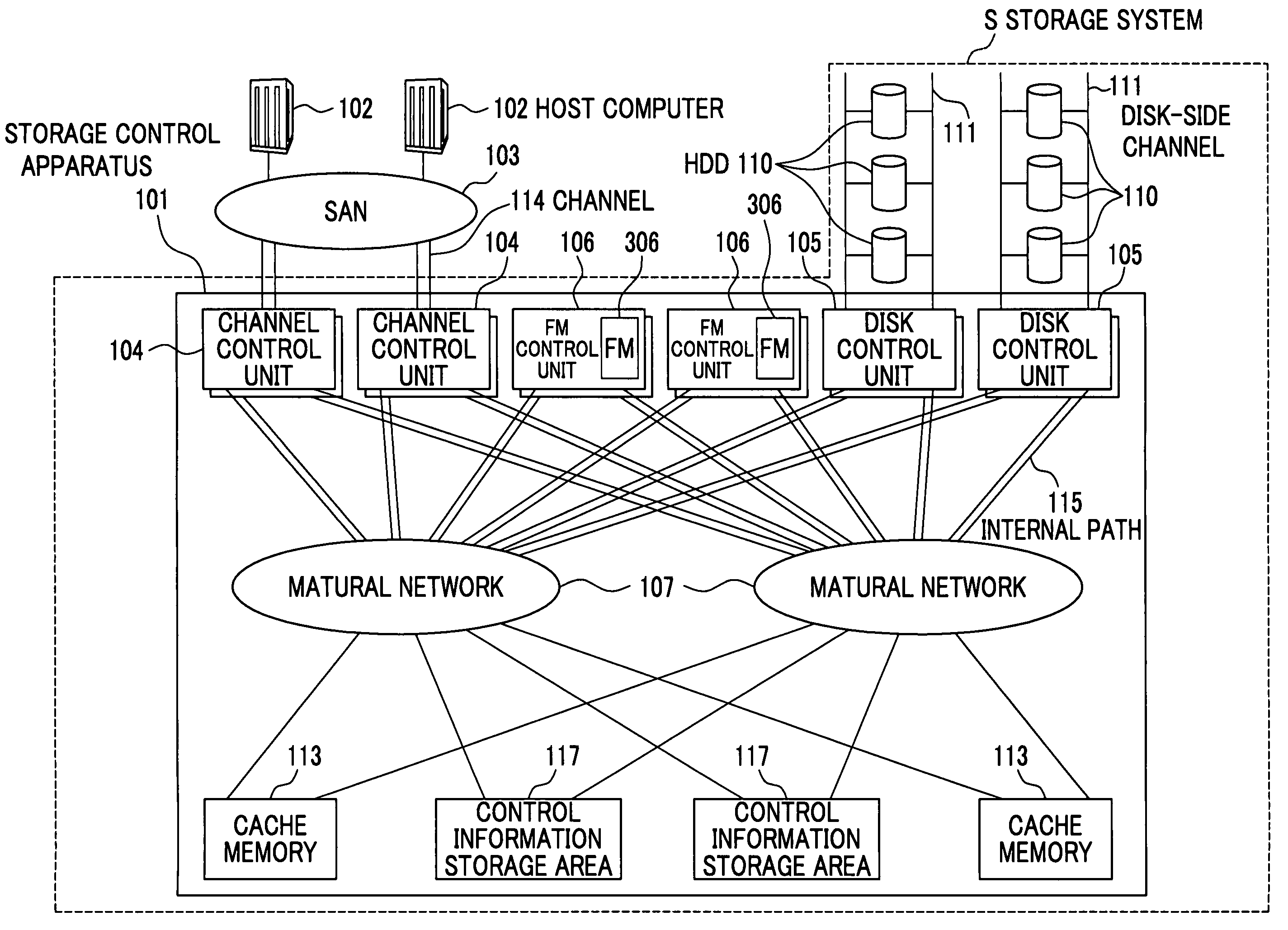
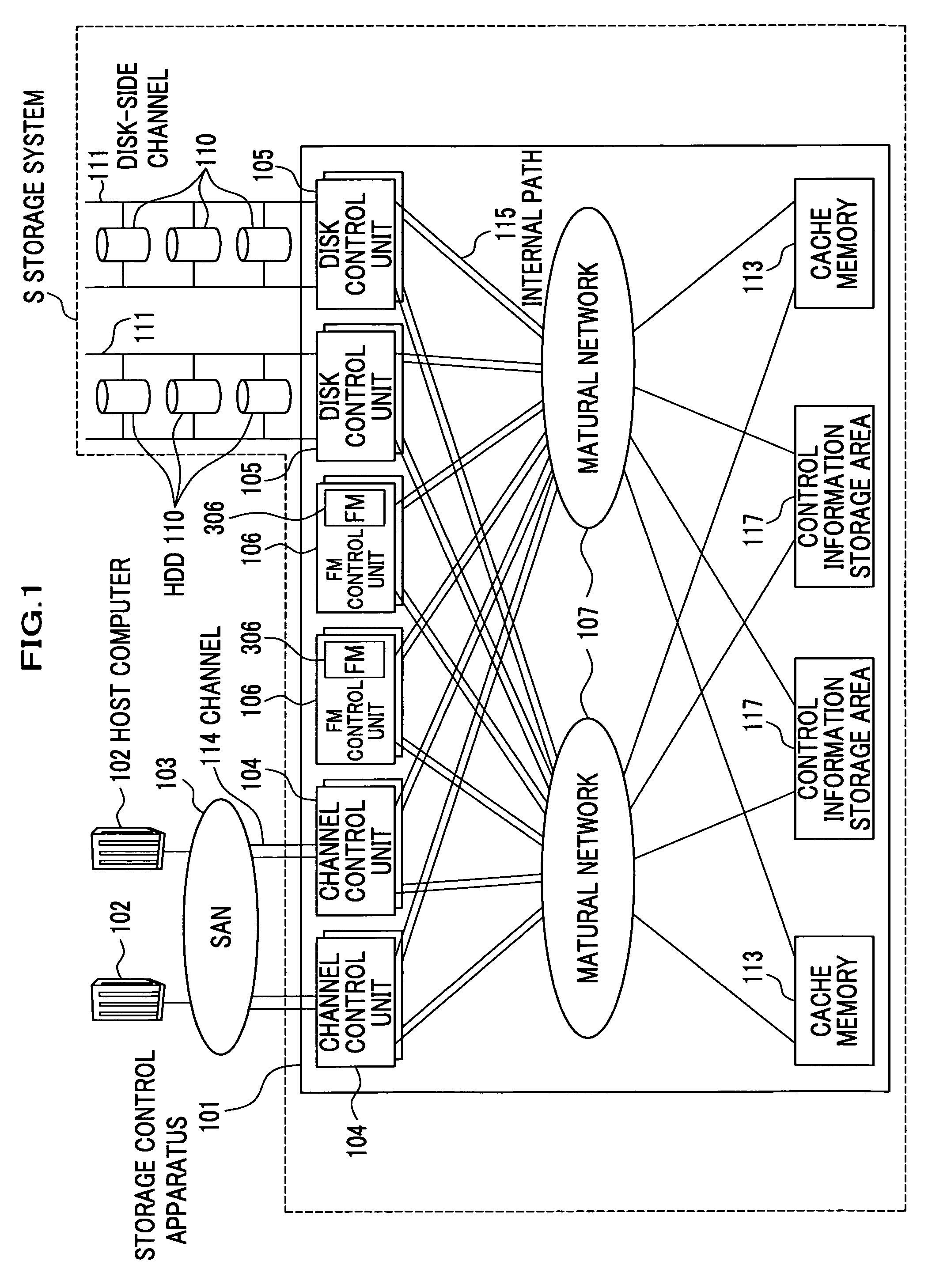
[0044]FIG. 1 is a block diagram showing an outline of a configuration of an embodiment of the present invention including a storage system. The storage system S comprises a storage control apparatus 101 and HDDs (hard disk drives) 110. The storage control apparatus 101 is connected through channels 114 via SAN (storage Area Network) 103 comprising SAN switches to one or plural host computers 102 (two in the drawing).

[0045]The storage control apparatus 101 is also connected to a plurality of HDDs 10 for storing data through disk-side channels 111. The storage control apparatus 101 comprises a plurality of channel control units (connecting units) 104, a plurality of cache memories (memory units) 113, control information storage areas (memory units) 117, a plurality of disk control units (connecting units) 105, a plural...


PUM


Abstract

A storage control apparatus according to the present invention includes a plurality of connecting units connected to one or more host computers and one or more hard disk drives as storage media for storing data, one or more non-volatile storage media which are of a different type from the hard disk drives and which store data WRITE requested from the host computer, a plurality of processing units for processing WRITE and READ requests from the host computer by using the hard disk drives or the non-volatile storage media and, a plurality of memory units for storing control information to be by the processing units.

Description

CROSS-REFERENCE TO RELATED APPLICATIONS[0001]This application claims the benefit of Japanese Patent Application 2005-275018 filed on Sep. 22, 2005, the disclosure of which is incorporated herein by reference.BACKGROUND OF THE INVENTION[0002]1. Field of the Invention[0003]The present invention relates to a technology for reducing power consumption in a storage control apparatus for storing data in at least one hard disk device and other storage media.[0004]2. Description of the Related Art[0005]In recent information business scenes such as data centers, it has been considered more important to reduce TCO (Total Cost of Ownership) in a storage system (general terms for storage control apparatuses and hard disk devices, etc.) In addition, it has been required for secured data storage for a long term. For example, banking agencies and medical institutions in Japan are obliged to accumulate their document data without deleting them by laws such as the Personal Information Protection Law....

Claims


Application Information

Patent Timeline
Patent Type & Authority Patents(United States)
IPC IPC(8): G06F13/00
CPCG06F3/0613G06F3/0616G06F3/0625G06F3/0649G06F3/067G06F3/0685G06F3/0631Y02B60/1246Y02D10/00
Inventor FUJIBAYASHI, AKIRAFUJIMOTO, KAZUHISANAKAMURA, SHUJI
Owner HITACHI LTD
Why Eureka
Try Eureka