Joint structure of branch connector for common rail

a branch connector and common rail technology, applied in the direction of hose connections, branching pipes, machines/engines, etc., can solve the problems of reducing the axial force cannot be increased, and the axial force cannot be raised, so as to increase the axial force and reduce the bending fatigue strength of the branch connector

Active Publication Date: 2009-08-04
USUI KOKUSAI SANGYO KAISHA LTD
View PDF35 Cites 7 Cited by
  • Summary
  • Abstract
  • Description
  • Claims
  • Application Information

AI Technical Summary

Benefits of technology

[0010]In the joint structure of the branch connector disclosed in Japanese Patent Application No. 2000-174009, when axial force is applied in the condition where the axial centers of the floating type sleeve washers as two split parts are not aligned with each other, force in the falling direction is generated on the boundary surface (contact surface) of both the sleeve washers and the axial force is lost. Additionally, when the branch connector tilts and a bending stress is generated, the stress concentrated on an end of an external opening of the washer caulked to the branch connector lowers the bending fatigue strength of the branch connector. There are still other problems in this example.
[0011]Wherefore, the invention has been particularly developed to solve the problems arising from the joint structure of the branch connector shown in JP-A-2001-82664. It is an object of the invention to provide a joint structure of a branch connector used in a common rail, which is capable of not only securing axial force applied to a seal surface and a sleeve washer but also increasing bending fatigue strength of the branch connector while avoiding a stress concentrated on an end of an external opening of the sleeve washer even when bending force or bending moment is applied to the branch connector due to vibration of an engine or a vehicle.
[0020]When a sleeve washer having a brim at its head is used as the sleeve washer included in the joint structure of the branch connector for the common rail according to the invention, sufficient contact surface between the sleeve washer and the tightening nut can be secured and thus larger axial force can be exerted than in the case that a brimless sleeve washer is used.
[0021]In the joint structure of the branch connector for the common rail according to the invention including the screw sleeve and the sleeve washer which has been externally fixed to the branch connector in advance to be combined therewith as one piece, the clearance formed by the tapered surface or the circular arc surface is provided between the inner surface of the sleeve washer at the external opening thereof and the outer surface of the branch connector. Thus, the branch connector can be flexibly bended in the vicinity of the end of the external opening of the sleeve washer, and bending fatigue strength of the branch connector can be secured since bending stress applied to the branch connector is not concentrated on the end of the external opening of the sleeve washer.

Problems solved by technology

Thus, the axial force cannot be increased.
Additionally, since the sleeve washer is outwardly expanded when the tightening nut is fastened, the axial force cannot be raised.
There are still other problems in this example.
Additionally, when the branch connector tilts and a bending stress is generated, the stress concentrated on an end of an external opening of the washer caulked to the branch connector lowers the bending fatigue strength of the branch connector.
There are still other problems in this example.

Method used


Image

  • Joint structure of branch connector for common rail
  • Joint structure of branch connector for common rail
  • Joint structure of branch connector for common rail

Examples


Embodiment Construction

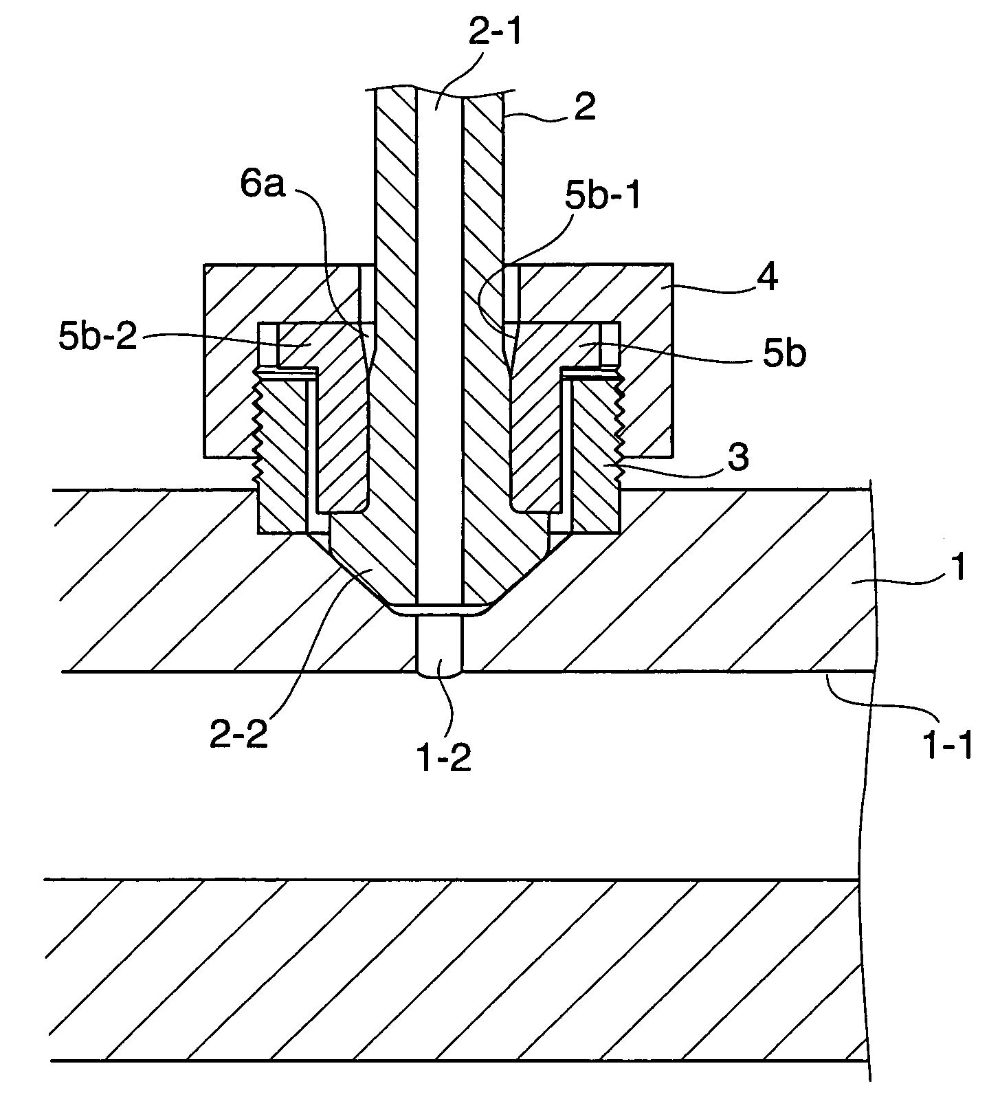
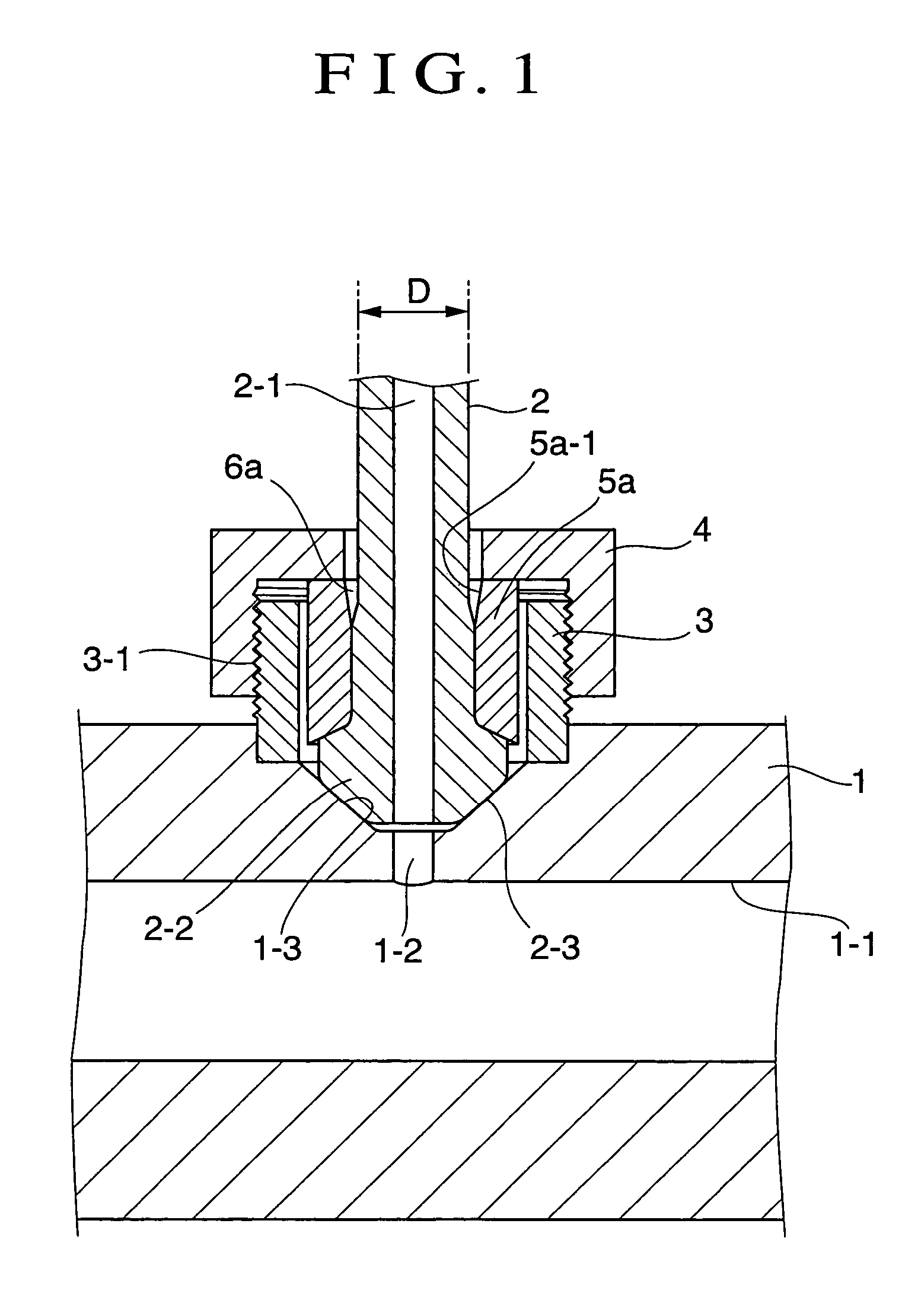
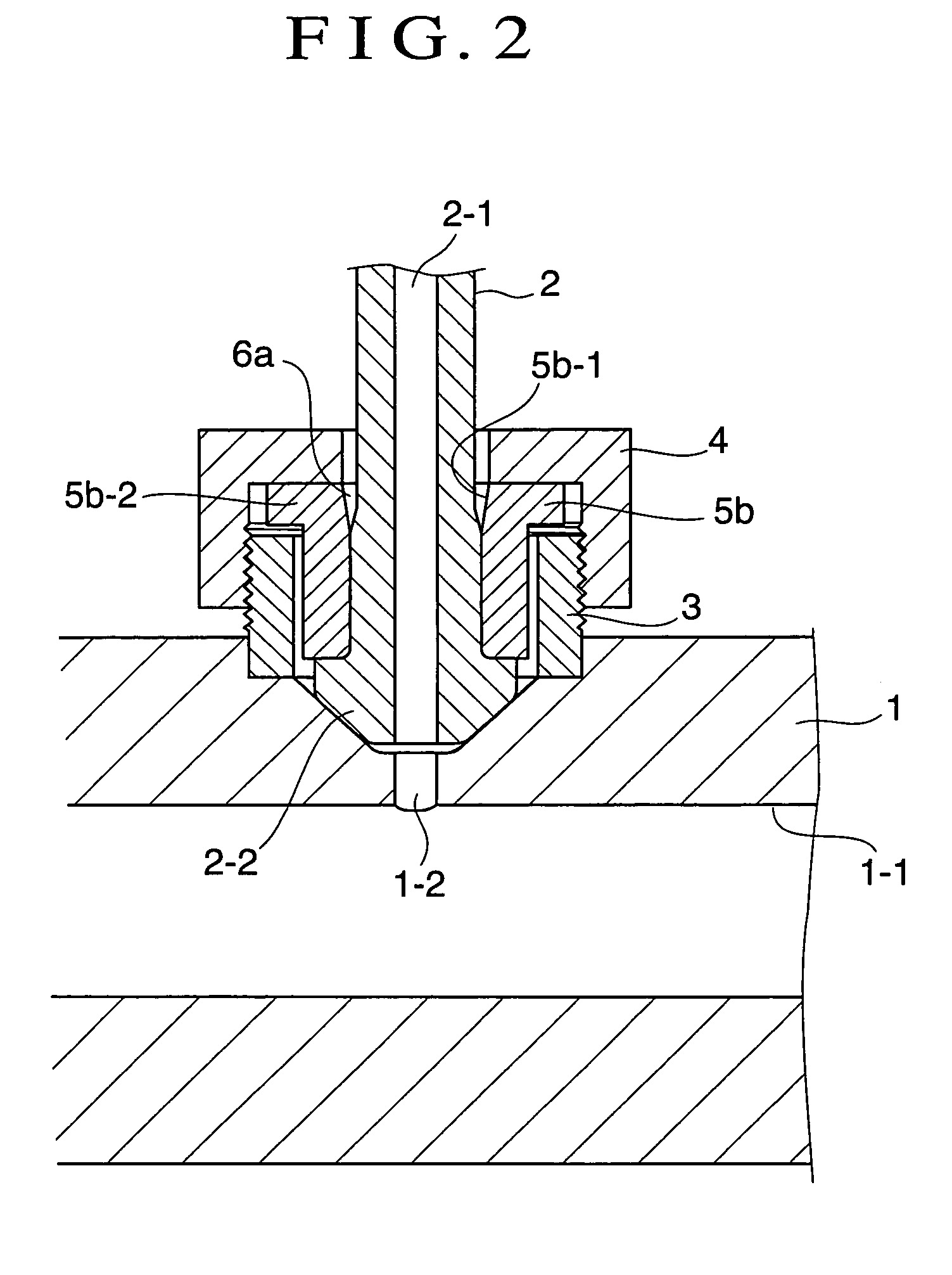
[0036]In FIGS. 1 through 9, a main pipe rail 1, a branch connector 2, a sleeve nipple 3, a tightening cap nut 4, sleeve washers 5a through 5d, clearances 6a and 6b according to the invention are shown.

[0037]The main pipe rail 1 as a common rail is a steel pipe for high pressure pipe arrangement which is made of SCM 435 or the like and includes a pipe-shaped portion having a relatively large thickness, which is 28 mm in diameter and 9 mm in thickness, for example. A flow passage 1-1 is provided within the main pipe rail 1 along its axial center.

[0038]A screw surface 3-1 is formed on the outer surface of the pipe-shaped sleeve nipple 3 as a joint. The screw surface 3-1 engages with the tightening cap nut 4 attached to the branch connector 2. The base end of the sleeve nipple 3 is directly welded or brazed to the outer peripheral wall of the main pipe rail 1. (The base end may be formed integrally with the main pipe rail 1 by forging.) In a subsequent finishing process, a branch hole 1...


PUM


Abstract

A joint structure of a branch connector for a common rail capable of securing axial force applied to a seal surface and a branch connector and increasing bending fatigue strength of the branch connector is provided. In the joint structure of the branch connector for the common rail which includes a screw sleeve concentric with a bearing surface of a main pipe rail and connects a branch connector to the main pipe rail via a sleeve washer which has been externally fixed to the branch connector in advance to be combined therewith as one piece, a clearance is provided between an inner surface of the sleeve washer at an external opening thereof and an outer surface of the branch connector.

Description

TECHNICAL FIELD[0001]The present invention relates to a joint structure of a branch connector formed by a branch pipe, a branch fitting or the like included in a common rail such as a high pressure fuel manifold which is typically used in an accumulator fuel injection system of a diesel internal combustion engine.BACKGROUND ART[0002]FIG. 10 illustrates an example of a joint structure of a branch connector of this type (see JP-A-10-213044). This branch connector has the following connecting structure. A pressure-receiving bearing surface 11-3 opening to the outside is formed at the position of a branch hole 11-2. The branch hole 11-2 provided on a peripheral wall of a main pipe rail 11 in the form of a circular pipe communicates with an internal flow passage 11-1. A screw sleeve (pipe-shaped sleeve nipple) 13 is welded or brazed to an outer peripheral wall of the main pipe rail 11 in the vicinity of the pressure-receiving bearing surface 11-3. A pressing bearing surface 12-3 is forme...

Claims


Application Information

Patent Timeline
Patent Type & Authority Patents(United States)
IPC IPC(8): F16L19/00F02M55/00F02M55/02F16L41/00F16L41/02F16L41/08F16L41/14
CPCF02M55/005F16L41/14F16L41/08F02M55/025F02M55/02
Inventor ASADA, KIKUO
Owner USUI KOKUSAI SANGYO KAISHA LTD
Why Eureka
Try Eureka