Turbocharger having two-stage compressor with boreless first-stage impeller

a technology of impeller and compressor, which is applied in the direction of positive displacement liquid engines, liquid fuel engines, piston pumps, etc., can solve the problems of the temperature of the impeller can be raised to a level that presents significant challenges to conventional aluminum alloy materials, and achieves low bore stresses and long service life.

Active Publication Date: 2009-08-04
GARRETT TRANSPORATION I INC
View PDF12 Cites 35 Cited by
  • Summary
  • Abstract
  • Description
  • Claims
  • Application Information

AI Technical Summary

Benefits of technology

[0010]Thus, the rotor assembly of the turbocharger defines three piloting features for ensuring the desired mutual concentricity and coaxial relationship between the impellers and between each impeller and the shaft. The first, second, and third pilot surfaces are non-threaded and serve to coaxially locate the impellers and shaft and constrain relative radial movement therebetween without constraining relative axial movement therebetween. Thus, the piloting features are not responsible for the fastening of the impellers to the shaft and to each other. Instead, the threads between the pilot member and the shaft accomplish the attachment function. By separating the attachment and piloting functions, improved concentricity and manufacturability can be achieved.

Problems solved by technology

However, because of the high pressure ratio entering the second-stage impeller, it has been found that the temperature of the impeller can be raised to a level that presents significant challenges to the conventional aluminum alloy materials typically used for compressor impellers.

Method used


Image

  • Turbocharger having two-stage compressor with boreless first-stage impeller
  • Turbocharger having two-stage compressor with boreless first-stage impeller
  • Turbocharger having two-stage compressor with boreless first-stage impeller

Examples


Embodiment Construction

[0016]The present inventions now will be described more fully hereinafter with reference to the accompanying drawings in which some but not all embodiments of the inventions are shown. Indeed, these inventions may be embodied in many different forms and should not be construed as limited to the embodiments set forth herein; rather, these embodiments are provided so that this disclosure will satisfy applicable legal requirements. Like numbers refer to like elements throughout.

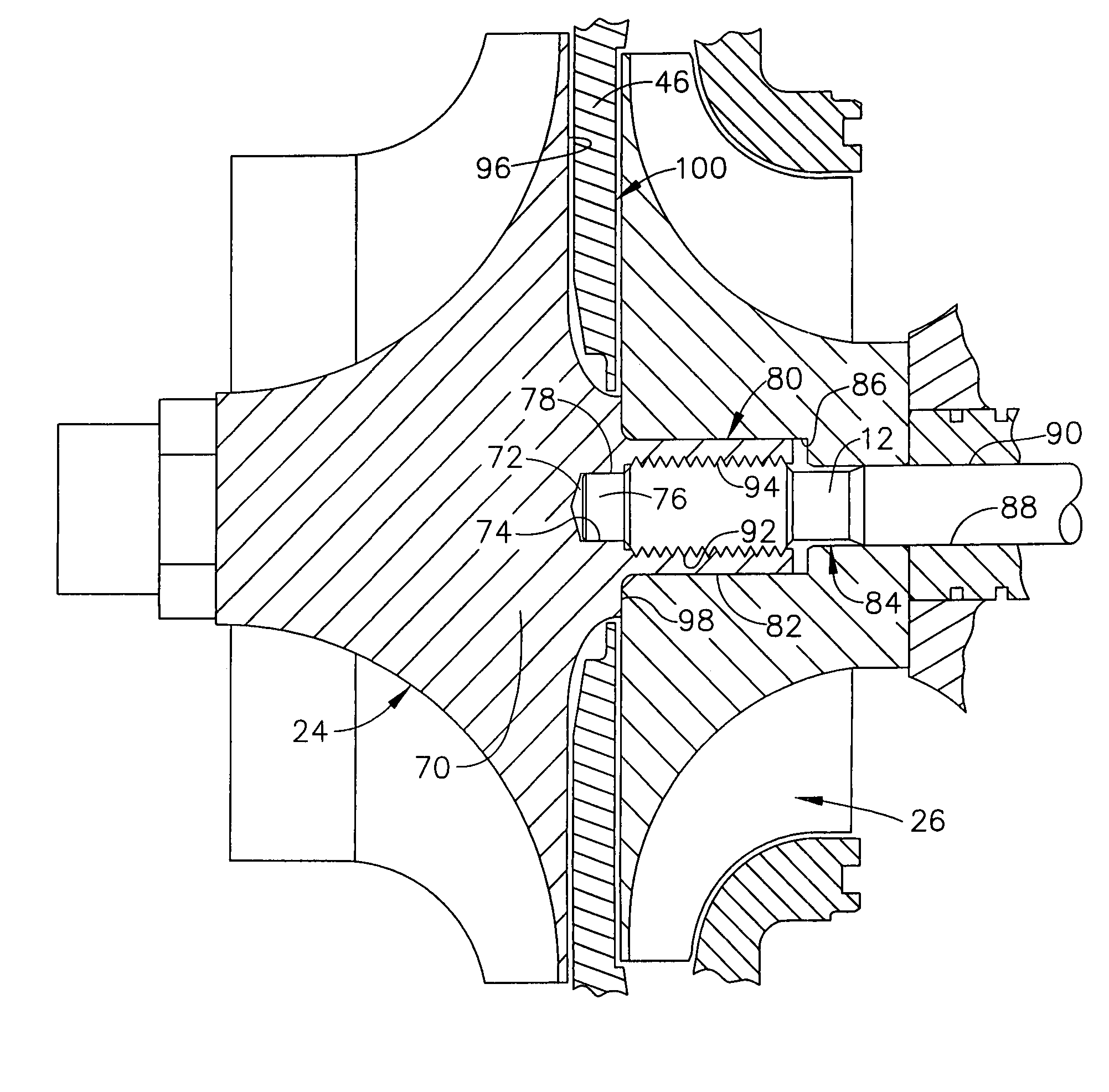
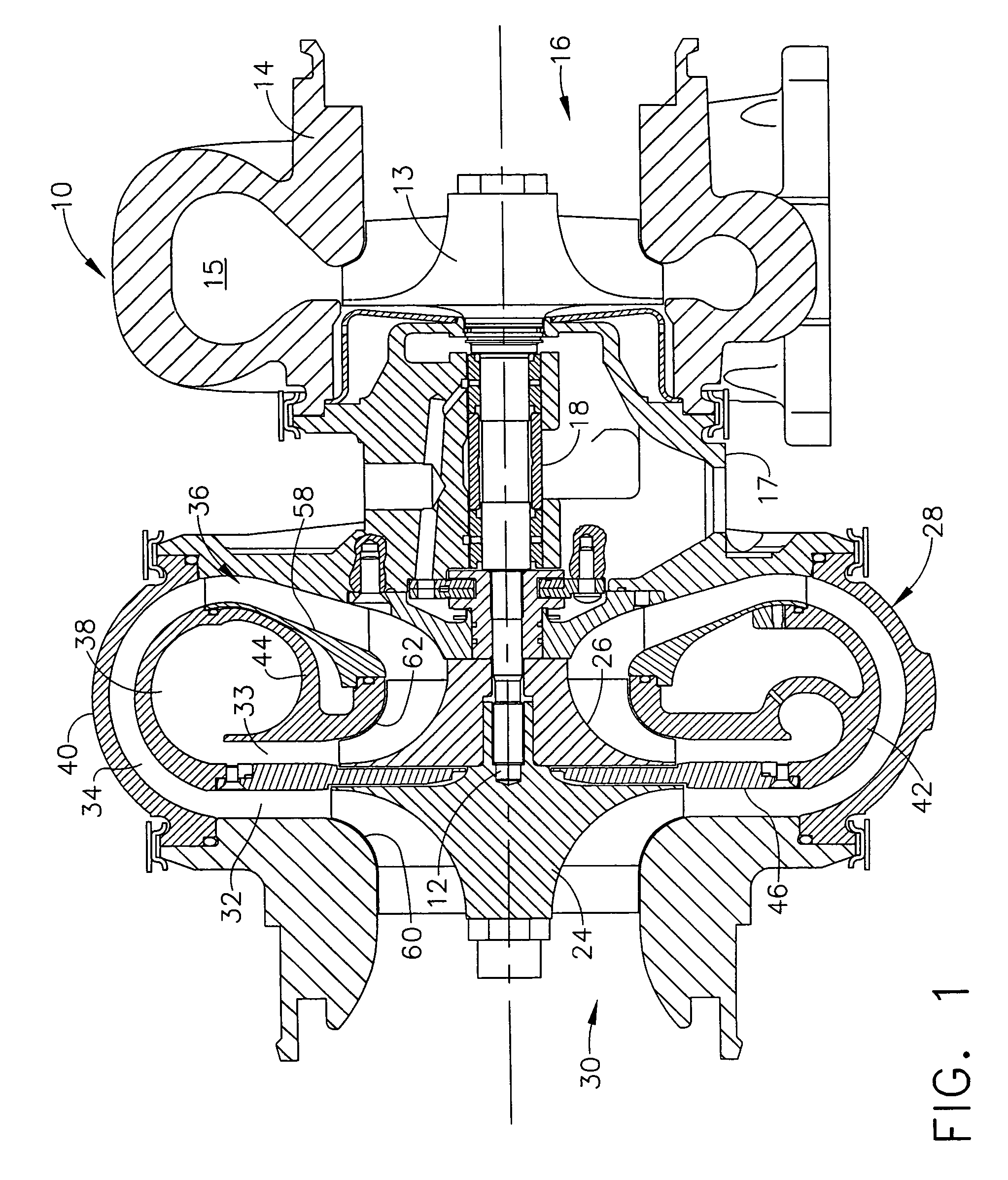
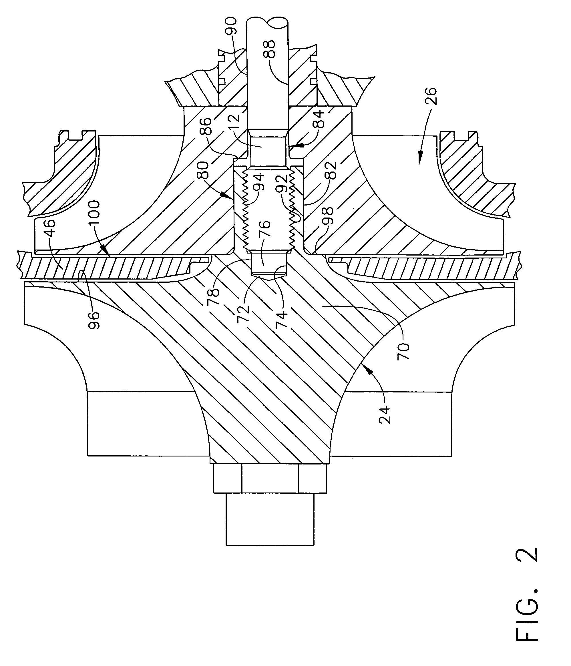
[0017]FIG. 1 shows a turbocharger 10 having a two-stage compressor in accordance with one embodiment of the invention. The turbocharger 10 has a configuration generally as described in U.S. Pat. No. 6,834,501, the disclosure of which is incorporated herein by reference. The turbocharger 10 includes a rotary shaft 12 on one end of which a turbine wheel 13 is mounted. The turbine section of the turbocharger 10 includes a turbine housing 14 that defines a turbine volute 15 arranged to direct fluid to the turbine wh...


PUM


Abstract

A turbocharger with a two-stage compressor having first- and second-stage impellers mounted on a common shaft in a back-to-back configuration. The first-stage impeller has a boreless configuration, defining an unthreaded pilot hole receiving an unthreaded end of the shaft so as to establish a coaxial relationship between the impeller and the shaft. The first impeller further defines a hollow cylindrical pilot member that projects from the back of the impeller and is received in a portion of the bore through the second-stage impeller to position the impellers coaxially with each other. The shaft passes through the pilot member and is externally threaded for engaging threads on the inner surface of the pilot member to secure the impellers to the shaft. The bore of the second impeller has a second portion that engages an outer cylindrical surface of the shaft to establish a coaxial relationship between the shaft and impeller.

Description

BACKGROUND OF THE INVENTION[0001]The present invention relates to turbochargers in general, and more particularly relates to high pressure ratio turbochargers employing a two-stage compressor having first- and second-stage impellers arranged in series.[0002]Developments in the turbocharger field continue to require increased pressure ratios for providing improved fuel economy, higher power ratings, and improved emissions performance for engines on which turbochargers are employed, particularly for commercial diesel application. With conventional turbocharger designs, the typical method for achieving such increased pressure ratios has been to increase the rotational speed of the compressor and turbine components. Current pressure-ratio capability for turbochargers of conventional design is typically in the 3.5 range, although some specialized designs can operate at about 4.0. Currently, the only known method for increasing the pressure-ratio capability of a compressor, for a given ma...

Claims


Application Information

Patent Timeline
Patent Type & Authority Patents(United States)
IPC IPC(8): F04D29/04
CPCF04D17/122F04D25/04F04D29/266F04D29/053F05B2220/40
Inventor ARNOLD, STEVEN D.VRBAS, GARY D.DULLACK, KRISTIAN N.THOMPSON, GLENN F.
Owner GARRETT TRANSPORATION I INC
Why Eureka
Try Eureka