Filter assembly for a reprocessor

a reprocessor and filter assembly technology, applied in the field of microbial deactivation of medical, dental, pharmaceutical, veterinary or mortuary instruments and devices, can solve problems such as microbial contamination accumulation, and achieve the effect of reducing the likelihood of microbial contamination of a water supply and high level of assuran

Inactive Publication Date: 2009-08-04
AMERICAN STERILIZER CO
View PDF16 Cites 12 Cited by
  • Summary
  • Abstract
  • Description
  • Claims
  • Application Information

AI Technical Summary

Benefits of technology

[0041]One advantage of the present invention is the provision of a sterilizable water filtration system for a reprocessing system.
[0042]Another advantage of the present invention is the provision of a microbially deactivated filtration system for a microbial deactivation system.
[0043]Another advantage of the present invention is the provision of a filtration system as described above that reduces the likelihood of microbial contamination of a water supply as a result of microbial growth in a filter element.
[0044]A still further advantage of the present invention is a filtration system as described above that is capable of providing a high level of assurance that the water that is supplied downstream of the second filter element is microbially deactivated or sterile.

Problems solved by technology

Although small amounts of the liquid sterilant may back-up to the downstream side of the filtration system, the upstream contents of the filtration system are generally not microbially deactivated and / or sterile.
Thus, there is a possibility that microbial contamination may accumulate in the upstream side of the filtration system over time, and subsequently pass into the downstream side of the filtration system and be introduced into the chamber during a rinse cycle.

Method used


Image

  • Filter assembly for a reprocessor
  • Filter assembly for a reprocessor
  • Filter assembly for a reprocessor

Examples


Embodiment Construction

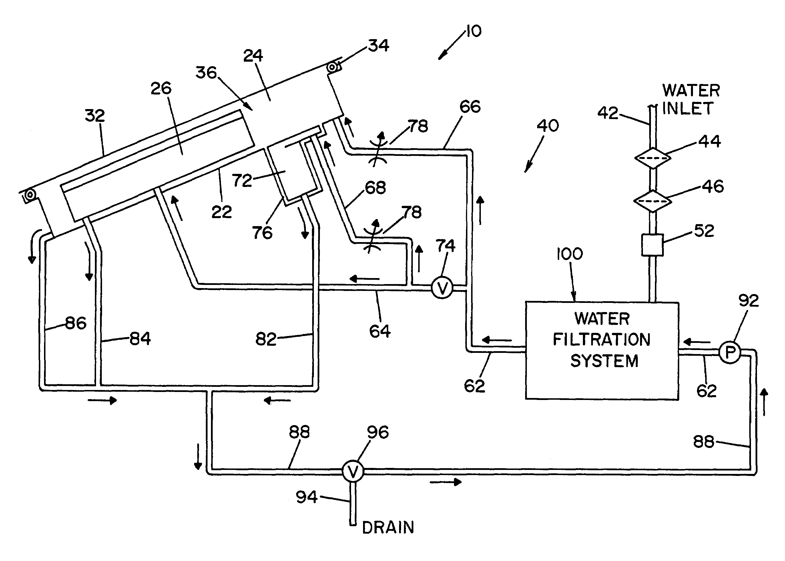
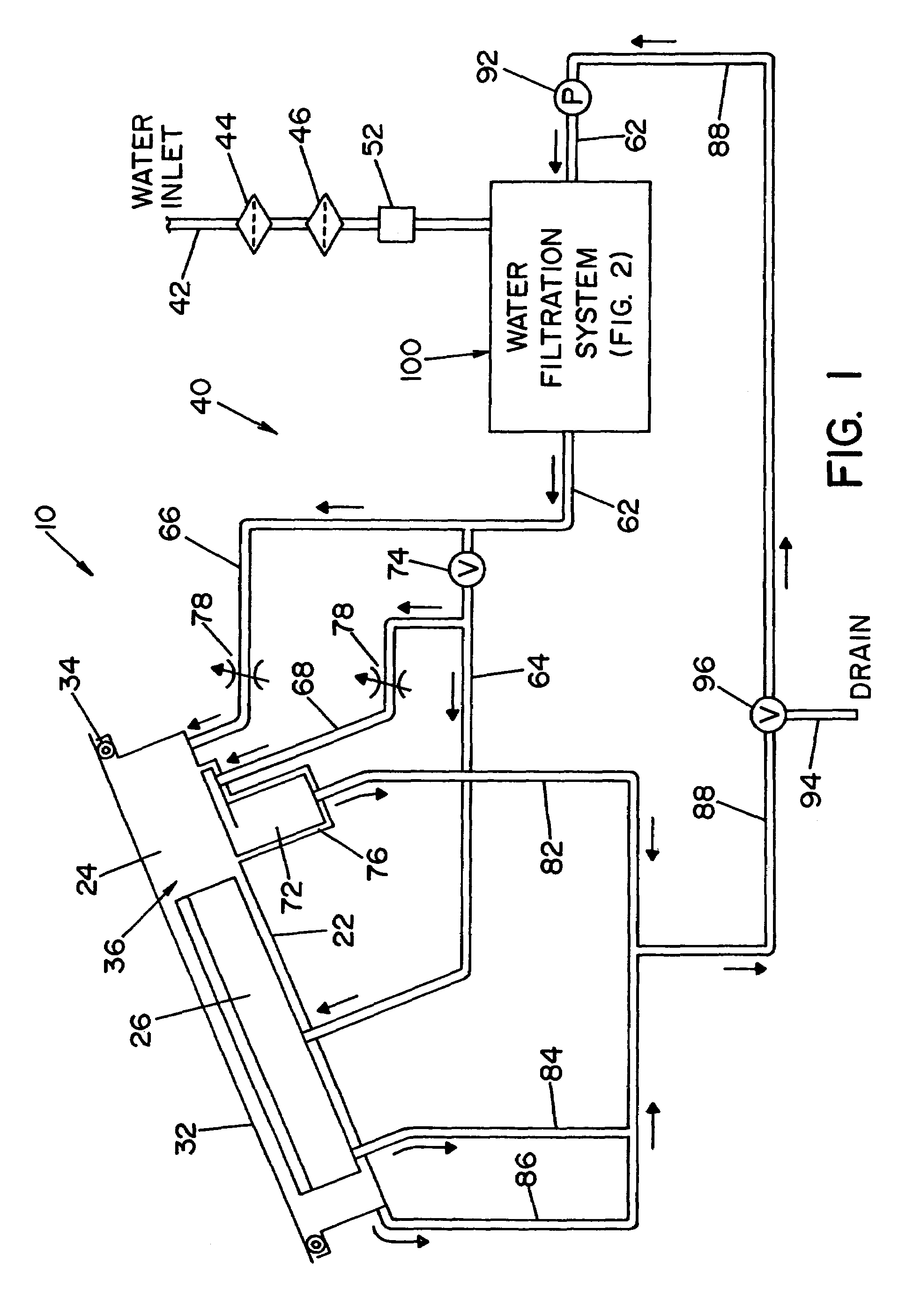
[0051]Referring now to the drawings wherein the showings are for the purpose of illustrating one embodiment of the invention only, and not for the purpose of limiting same, FIG. 1 shows a simplified, schematic piping diagram of a microbial deactivation apparatus 10 illustrating one embodiment of the present invention.

[0052]A panel 22, that is part of a housing structure (not shown), defines a recess or cavity 24 dimensioned to receive items or instruments to be microbially deactivated. In the embodiment shown, a tray or container 26 is provided to receive the devices or instruments to be deactivated. Container 26 is dimensioned to be received within recess or cavity 24, as illustrated in FIG. 1.

[0053]A manually operable lid 32 is movable between an opened position allowing access to cavity 24, and a closed position (shown in FIG. 1) closing or covering cavity 24. A seal element 34 surrounds cavity 24 and forms a fluid-tight, i.e., an airtight and liquid-tight, seal between lid 32 an...


PUM

PropertyMeasurementUnit
temperatureaaaaaaaaaa

Abstract

The present invention provides a method of operating a reprocessor that has a chamber for receiving items to be sterilized. The reprocessor is filled with water that has passed through a first and a second filter element that both comprise a filtration system. A liquid sterilant is generated by mixing the water with dry chemical reagents. The liquid sterilant is circulated through a fluid circulation system and the filtration system wherein a portion of the liquid sterilant is directed through a bypass conduit and another portion is directed through the first and second filter elements. After a predetermined exposure time, the reprocessor is drained. Then the reprocessor is filled with water for rinsing that has passed through the first and the second filter elements. The water for rinsing is heated prior to being introduced into the reprocessor.

Description

RELATED APPLICATIONS[0001]The present invention is a Continuation-in-Part (CIP) of U.S. application Ser. No. 10 / 633,343 filed Aug. 1, 2003 now U.S. Pat. No. 7,135,142, entitled “Filter Assembly for a Reprocessor” which is incorporated herein by reference in its entirety.FIELD OF THE INVENTION[0002]The present invention relates to microbial deactivation of medical, dental, pharmaceutical, veterinary or mortuary instruments and devices, and more particularly to a filtration system for use in a liquid microbial deactivation system.BACKGROUND OF THE INVENTION[0003]Medical, dental, pharmaceutical, veterinary or mortuary instruments and devices that are exposed to blood or other body fluids require thorough cleaning and microbial deactivation or sterilization between each use. Liquid microbial deactivation systems are now widely used to clean and deactivate instruments and devices that cannot withstand the high temperatures of a steam sterilization system. Liquid microbial deactivation sy...

Claims


Application Information

Patent Timeline
Patent Type & Authority Patents(United States)
IPC IPC(8): A61L2/18A61L2/02A61L2/16C02F1/44C02F1/50C02F1/68C02F1/72C02F9/00
CPCA61L2/022A61L2/16C02F9/005A61L2/18C02F2301/08C02F9/00C02F1/722C02F1/02C02F1/444C02F1/50C02F1/688C02F1/001C02F1/32C02F1/44C02F9/20
Inventor BURKE, PETER A.LUDWIG, KARL F.KRAL, JUDE A.ZELINA, FRANCIS J.
Owner AMERICAN STERILIZER CO
Why Eureka
Try Eureka