Dual-screen digital radiographic imaging detector array

a detector array and digital radiographic imaging technology, applied in the field of digital radiography, can solve the problems of loss of spatial resolution of medical x-ray detectors employing scintillating phosphor screens to absorb x-rays and produce light, and achieve the effects of reducing the loss of spatial resolution, and improving the quality of imag

Active Publication Date: 2009-08-04
CARESTREAM HEALTH INC
View PDF14 Cites 45 Cited by
  • Summary
  • Abstract
  • Description
  • Claims
  • Application Information

AI Technical Summary

Benefits of technology

[0017]An advantage of the invention is that it allows DR imaging to combine a first image optimized for Modulation Transfer Function (MTF) with a second image optimized for sensitivity in order to obtain an x-ray image with higher quality in a DR imaging system.
[0018]In one embodiment of the invention, a radiographic imaging device comprises a first scintillating phosphor screen having a first thickness; a second scintillating phosphor screen having a second thickness; a substrate disposed between the first and second screens, the substrate being substantially transparent to X-rays used with the device; and an imaging array disposed between a first side of the substrate and one of the first and second screens, the imaging array comprising a plurality of pixels, each pixel including at least one photosensor and at least one readout element. The readout element may be a thin-film transistor formed on one side of the substrate. As used in this specification, “substantially transparent” means that X-rays pass through the substrate in an ample or considerable amount sufficient for detection by the photosensor to produce a radiographic image.
[0019]In another embodiment, a radiographic imaging device comprises a substrate substantially transparent to X-rays used with the device; a first scintillating phosphor screen having a first thickness disposed on a first side of the substrate; a second scintillating phosphor screen having a second thickness disposed on a second side of the substrate, so that the substrate is between the first and second scintillating phosphor screens; the substrate being transparent to light emitted from the first and second screens; and an imaging array formed on one side of the substrate, the imaging array comprising a first group of photosensors primarily sensitive to light emitted from the first screen; and a second group of photosensors primarily sensitive to light emitted from the second screen.
[0020]The asymmetric dual-screen digital radiography apparatus of the present invention has various advantages over a single-screen digital radiography apparatus. The higher spatial frequency response, or MTF of the apparatus of the present invention yields sharper images. The higher X-ray absorption yields higher detector speed. The lower noise levels of the exemplary apparatus of the present invention give less quantum mottle. The higher detective quantum efficiency (DQE) of the embodiments of the present invention provides higher overall image quality. Furthermore, the use of a pair of asymmetric screens in an indirect DR apparatus significantly eases the conflict in the design of an X-ray phosphor screen to simultaneously maintain both a good level of X-ray absorption (which in general requires a screen with increased thickness) and high spatial resolution (which in general requires a screen with decreased thickness). Moreover, the use of a flexible substrate (e.g., metal foil, plastic sheet, or combinations thereof) for the flat panel imaging apparatus improves the mechanical strength and physical durability of the apparatus, and reduces the X-ray absorption loss due to the substrate.
[0021]In all of the above-identified embodiments of the invention, a single imaging array is used to sense both screens. Within each pixel, one or more photodiodes are used to image the first screen and one or more photodiodes are used to image the second screen. The use of a single readout array guarantees precise registration of the images of the two screens, provides a thinner and more robust panel assembly than the use of multiple panels, and requires less support electronics, in particular fewer row drivers and column amplifiers and digitizers.

Problems solved by technology

Generally, medical X-ray detectors employing a scintillating phosphor screen to absorb X-rays and produce light suffer the loss of spatial resolution due to lateral light diffusion in the phosphor screen.

Method used


Image

  • Dual-screen digital radiographic imaging detector array
  • Dual-screen digital radiographic imaging detector array
  • Dual-screen digital radiographic imaging detector array

Examples


Embodiment Construction

[0041]Reference is made to commonly assigned, copending U.S. patent application Ser. No. 12 / 025,086 filed Feb. 4, 2008 by Tredwell entitled DIGITAL RADIOGRAPHIC IMAGING APPARATUS.

[0042]The present description is directed in particular to elements forming part of, or cooperating more directly with, apparatuses in accordance with the invention. It is to be understood that elements not specifically shown or described may take various forms well known to those skilled in the art. In the description that follows, terms and phrases such as “above” or “on top of” are used in a broad sense, to indicate an arrangement of layers relative to each other. Certainly, an X-ray imaging plate may be exposed in any orientation, where stacked layers extend in generally horizontal, vertical, or oblique directions.

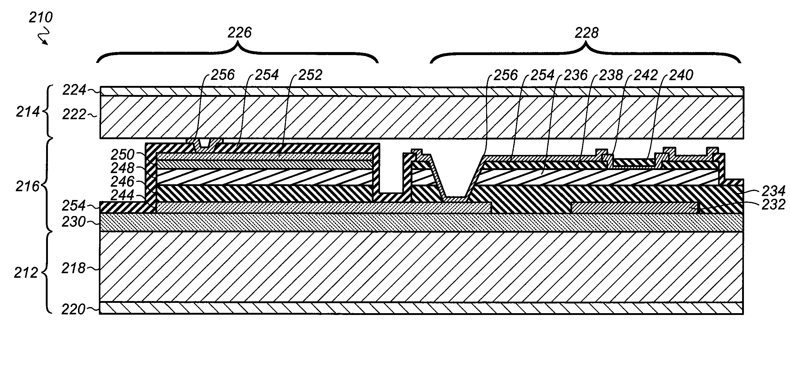
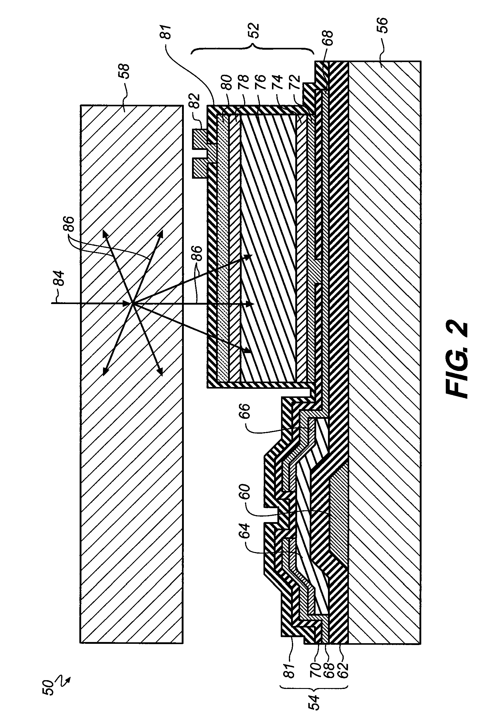
[0043]FIGS. 5 to 17 show diagrammatic views of various digital imaging devices in accordance with the present invention. A schematic cross-section of a first exemplary embodiment of the invent...


PUM


Abstract

A radiographic imaging device has a first scintillating phosphor screen having a first thickness and a second scintillating phosphor screen having a second thickness. A transparent substrate is disposed between the first and second screens. An imaging array formed on a side of the substrate includes multiple photosensors and an array of readout elements.

Description

CROSS REFERENCE TO RELATED APPLICATION[0001]This application is a continuation-in-part of co-pending, commonly assigned U.S. patent application Ser. No. 11 / 487,539 filed Jul. 14, 2006 by Yorkston, et al, entitled APPARATUS FOR ASYMMETRIC DUAL-SCREEN DIGITAL RADIOGRAPHY.FIELD OF THE INVENTION[0002]The invention relates generally to digital radiography, and in particular relates to the use of dual, asymmetric phosphor screens in a digital radiographic flat-panel imaging detector array to improve image quality.BACKGROUND OF THE INVENTION[0003]Generally, medical X-ray detectors employing a scintillating phosphor screen to absorb X-rays and produce light suffer the loss of spatial resolution due to lateral light diffusion in the phosphor screen. To reduce lateral light diffusion and maintain acceptable spatial resolution, the phosphor screens must be made sufficiently thin. The spatial resolution and X-ray detection ability of an imaging apparatus are often characterized by the modulatio...

Claims


Application Information

Patent Timeline
Patent Type & Authority Patents(United States)
IPC IPC(8): G01T1/20A61B6/00H01L27/14H04N5/32
CPCG01T1/2018G21K4/00H01L27/1464H01L27/14663H01L27/14632G21K2004/04H01L27/14636G01T1/20183G01T1/20181G01T1/20A61B6/00H04N5/32H01L27/14
Inventor TREDWELL, TIMOTHY JOHNKERR, ROGER STANLEYKULPINSKI, ROBERT W.YORKSTON, JOHNWOJCIK, TIMOTHY JOHNYIP, KWOK-LEUNG
Owner CARESTREAM HEALTH INC
Why Eureka
Try Eureka