Thermal overload protection circuit and method for protecting switching power amplifier circuits

a protection circuit and power amplifier technology, applied in the direction of electronic switching, emergency protection circuit arrangement, pulse technique, etc., can solve the problems of minority carrier injection into the substrate, device turning, latch-up and failure of the integrated circuit, etc., and achieve the effect of reducing the stored energy in the inductan

Active Publication Date: 2009-08-04
CIRRUS LOGIC INC
View PDF8 Cites 30 Cited by
  • Summary
  • Abstract
  • Description
  • Claims
  • Application Information

AI Technical Summary

Benefits of technology

[0012]The switching power amplifier integrated circuit includes a control circuit that has a timer. The timer is activated when a thermal overload indication is received. Until the timer expires, the circuit controlling the switching power stage of the amplifier forces the duty cycle of the switching operation toward a fifty-percent duty cycle, thereby reducing the stored energy in the inductance of a load coupled to the switching power output stage, which may include both filter inductance and any load inductance. After the timer has expired, the switching power stage is disabled. In an alternative embodiment, the timer may be omitted, and the current through the load inductance measured. The switching power stage is disabled after the magnitude of the current has fallen below a predetermined threshold.

Problems solved by technology

However, since the load (including output filtering components) is typically inductive, energy is stored in the inductance of the load and a back-current will occur when the drive transistors are turned off.
Therefore, minority carrier injection into the substrate is undesirable in that other devices may be turned on or disrupt the operation of another circuit, for example, changing the state of a stored logical value.
In the power output stage, the minority carriers in one device can cause a control change in the complementary device that through feedback turns both parasitic devices on, causing latch-up and failure of the integrated circuit.
Therefore, minority carrier injection into the N-well is undesirable in that other devices may be turned on, or disrupt the operation of another circuit.
In the power output stage, the minority carriers in one device can cause a control change in the complementary device that through feedback turns both parasitic devices on, causing latch-up and failure of the integrated circuit.
Further, such guard rings are applicable only in applications in which the power devices are integrated on the same substrate with the guard rings, and therefore will not provide protection for circuits having separate monolithic driver devices, unless the guard rings are integrated in the driver device package itself.

Method used


Image

  • Thermal overload protection circuit and method for protecting switching power amplifier circuits
  • Thermal overload protection circuit and method for protecting switching power amplifier circuits
  • Thermal overload protection circuit and method for protecting switching power amplifier circuits

Examples


Embodiment Construction

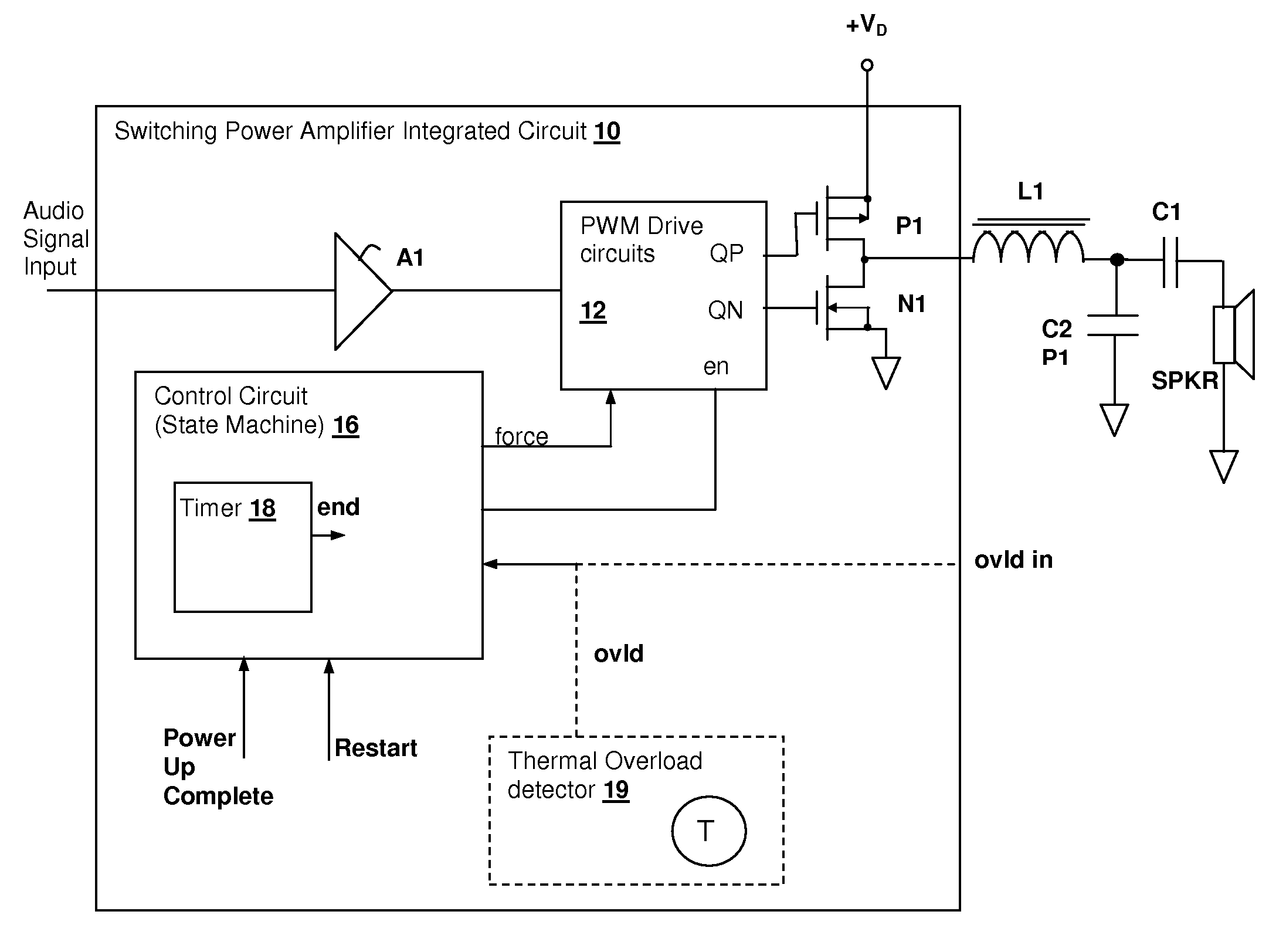
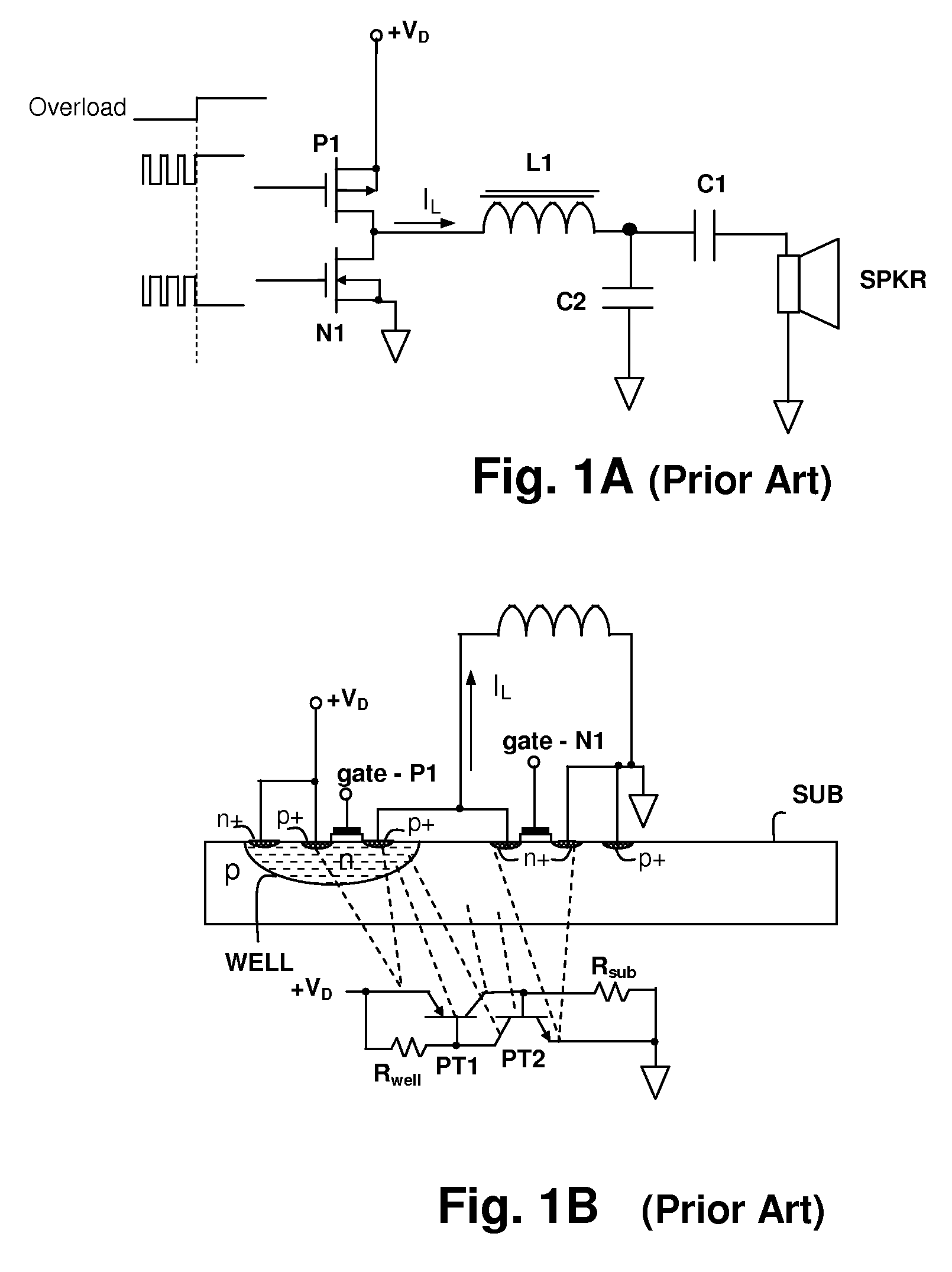
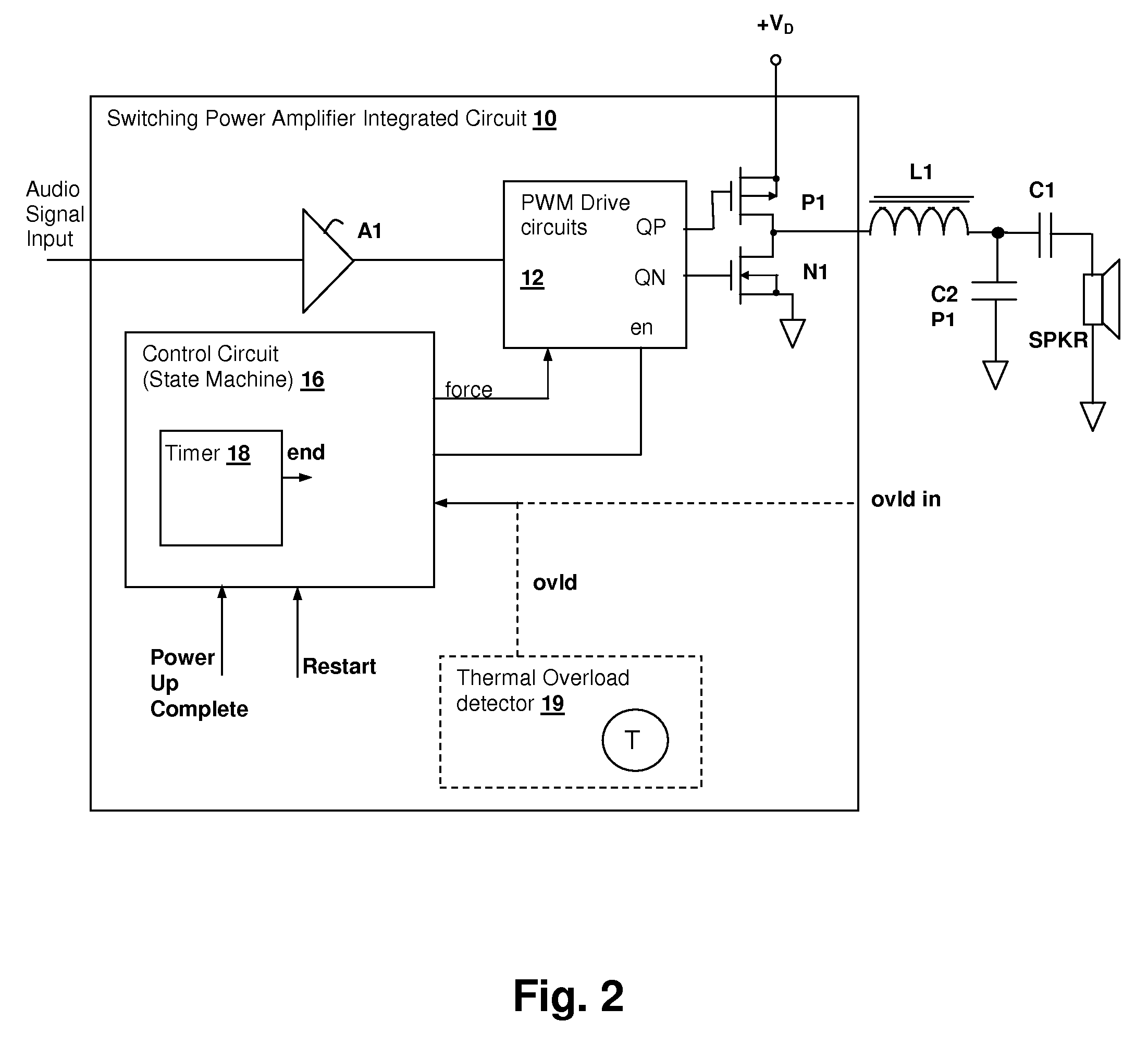
[0022]The present invention encompasses a circuit and method of operation that discharges stored inductive energy from filter inductors and load inductances coupled to the output of a switching power amplifier prior to disabling the switching power stage in response to detection of a thermal overload condition. The circuit and method thereby prevent latch-up and consequent circuit failure that can be caused by discharge of stored magnetic energy from the inductances into the disabled power stage transistors. The discharging is performed by forcing the duty cycle of the output stage toward a fifty-percent duty cycle for a predetermined time period. The forcing may immediately impose a fifty-percent duty cycle, or there may be a gradual change from the duty cycle at the time of receipt of a thermal overload indication toward the fifty-percent duty cycle level.

[0023]It is not required that the duty cycle actually reach fifty-percent for the invention to protect the switching power stag...


PUM


Abstract

A thermal overload protection circuit and method for protecting switching power amplifier circuits provides protection against latch-up and other failures due to energy returned from an inductive load when the amplifier output is disabled in response to a thermal overload condition. Upon detection of a thermal overload condition, rather than immediately disabling the switching power output stage, the switching power output stage is driven toward a fifty-percent duty cycle of operation for a predetermined time period so that energy stored in inductance of the load is reduced, preventing back-currents that would otherwise may cause latch-up within the integrated circuit when the switching power output stage is disabled. After the time period has elapsed, the switching power output stage is disabled. Alternatively, the current through the inductive load is measured and the switching power stage is disabled after the magnitude of the current has fallen below a threshold.

Description

CROSS-REFERENCE TO RELATED PATENT APPLICATIONS[0001]The present U.S. Patent Application is related to U.S. patent application Ser. No. 11 / 862,324 entitled “PROTECTION CIRCUIT AND METHOD FOR PROTECTING SWITCHING POWER AMPLIFIER CIRCUITS DURING RESET”, filed concurrently herewith, and to U.S. patent application Ser. No. 11 / 862,481 entitled “OVER-CURRENT PROTECTION CIRCUIT AND METHOD FOR PROTECTING SWITCHING POWER AMPLIFIER CIRCUITS” also filed concurrently herewith. Both of the above-referenced U.S. Patent Applications are incorporated herein by reference, have at least one common inventor, and are assigned to the same Assignee.BACKGROUND OF THE INVENTION[0002]1. Field of the Invention[0003]The present invention relates generally to integrated circuit switching power amplifiers, and more specifically, to a circuit and method for protecting against latch-up failures when a switching power amplifier output stage is disabled in response to detection of a thermal overload.[0004]2. Backgro...

Claims


Application Information

Patent Timeline
Patent Type & Authority Patents(United States)
IPC IPC(8): H03F1/52
CPCH03F1/523H03F3/2173H03K2017/0806H03K17/6872H03K17/0822
Inventor GABORIAU, JOHANNZHANG, LINGLIBOUDREAUX, RANDY
Owner CIRRUS LOGIC INC
Why Eureka
Try Eureka