Over-current protection circuit and method for protecting switching power amplifier circuits

Active Publication Date: 2009-06-30
CIRRUS LOGIC INC
View PDF8 Cites 41 Cited by
  • Summary
  • Abstract
  • Description
  • Claims
  • Application Information

AI Technical Summary

Benefits of technology

[0012]The switching power amplifier integrated circuit includes a control circuit that has a timer. When an over-current condition is detected, the transistor(s) having a conduction direction corresponding to the over-current direction is disabled, and a timer is activated. Until the timer expires, the circuit controlling the switching power stage of the amplifier turns on the transistor(s) having a conduction direction opposite the over-current direction, thereby reducing the stored ene

Problems solved by technology

However, since the load (including output filtering components) is typically inductive, energy is stored in the inductance of the load and a back-current will occur when the drive transistors are turned off.
Therefore, minority carrier injection into the substrate is undesirable in that other devices may be turned on or disrupt the operation of another circuit, for example, changing the state of a stored logical value.
In the power output stage, the minority carriers in one device can cause a control change in the complementary device that through feedback turns both parasitic devices on, causing latch-up and failure of the integrated circuit.
Therefore, minority carrie

Method used


Image

  • Over-current protection circuit and method for protecting switching power amplifier circuits
  • Over-current protection circuit and method for protecting switching power amplifier circuits
  • Over-current protection circuit and method for protecting switching power amplifier circuits

Examples


Embodiment Construction

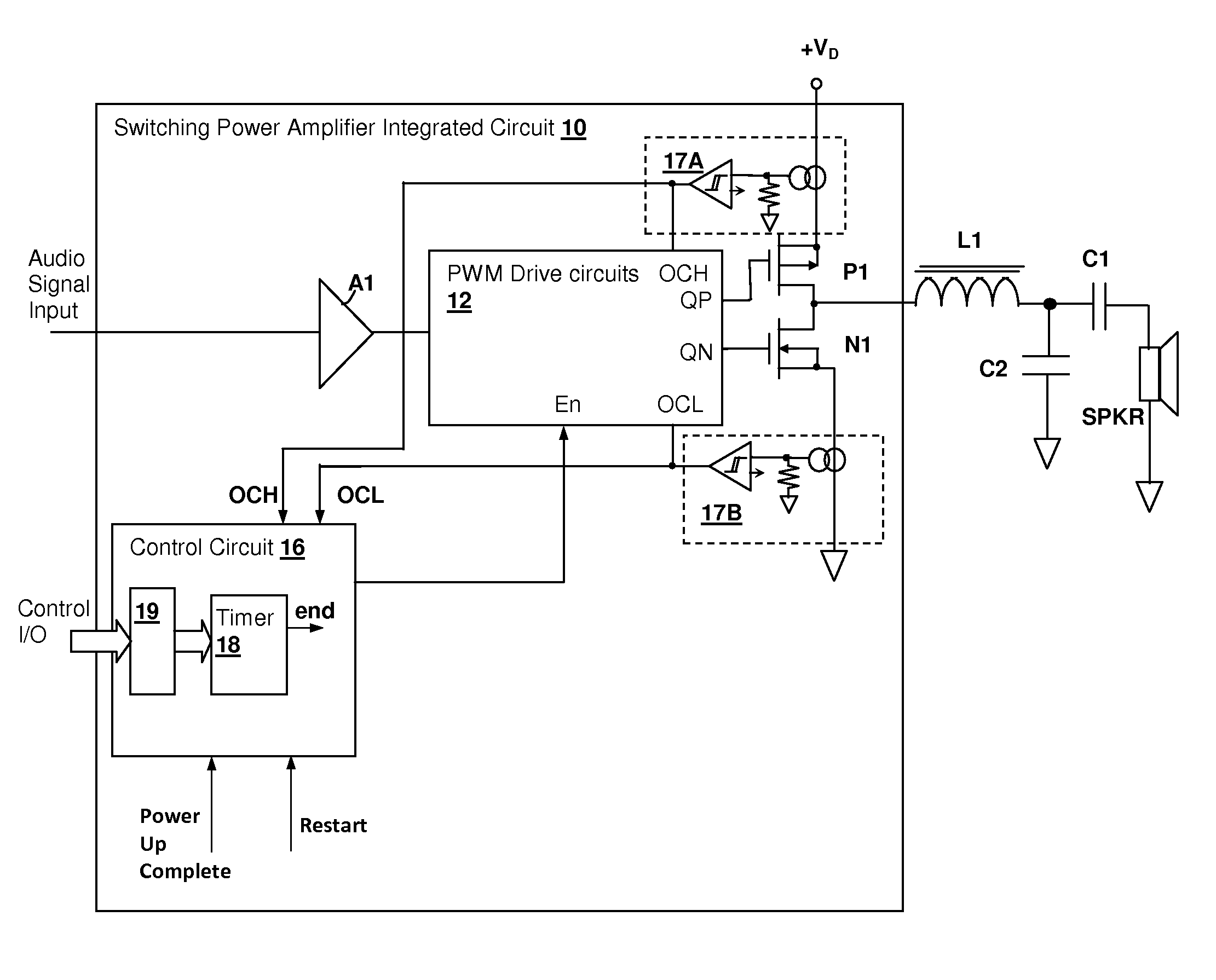
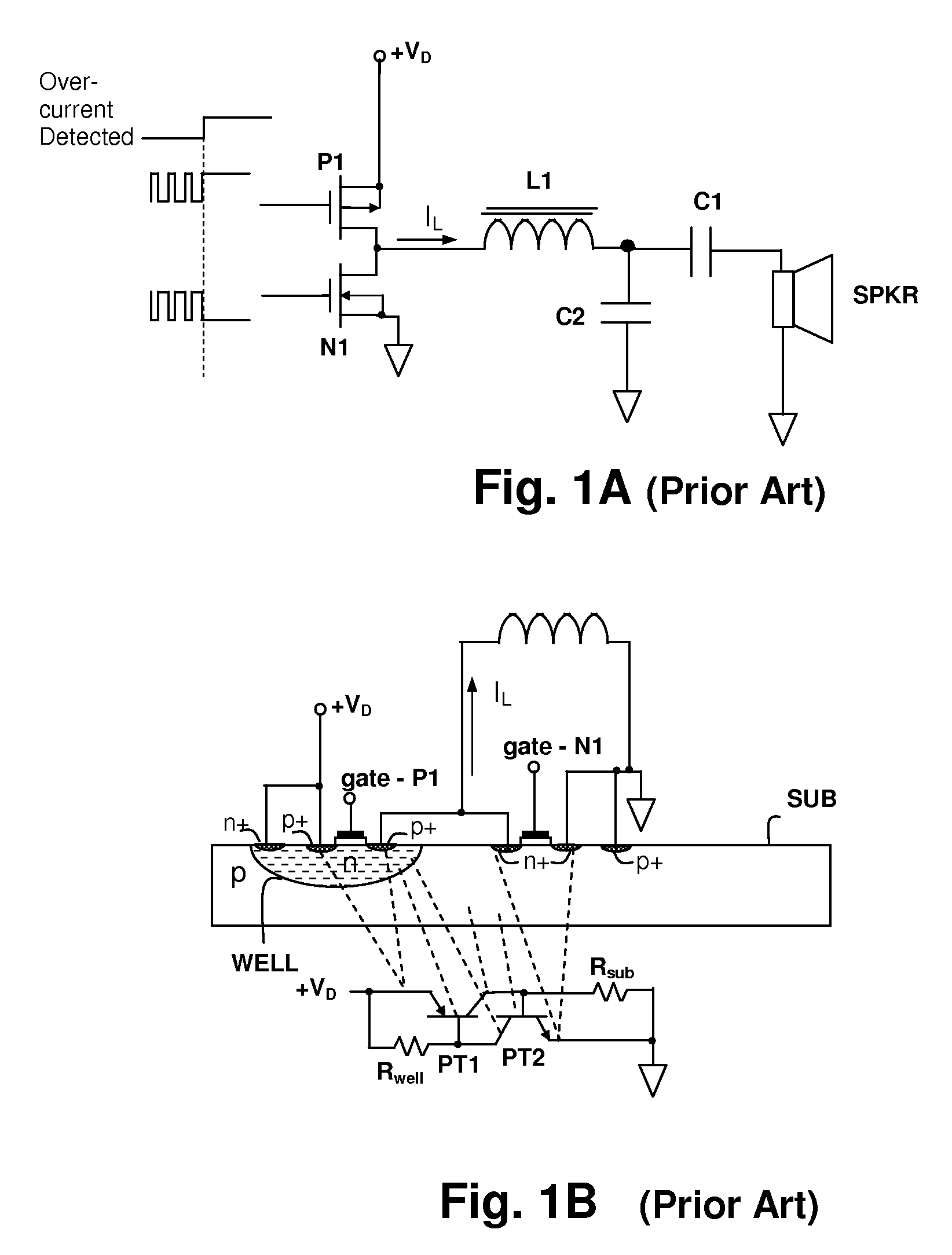
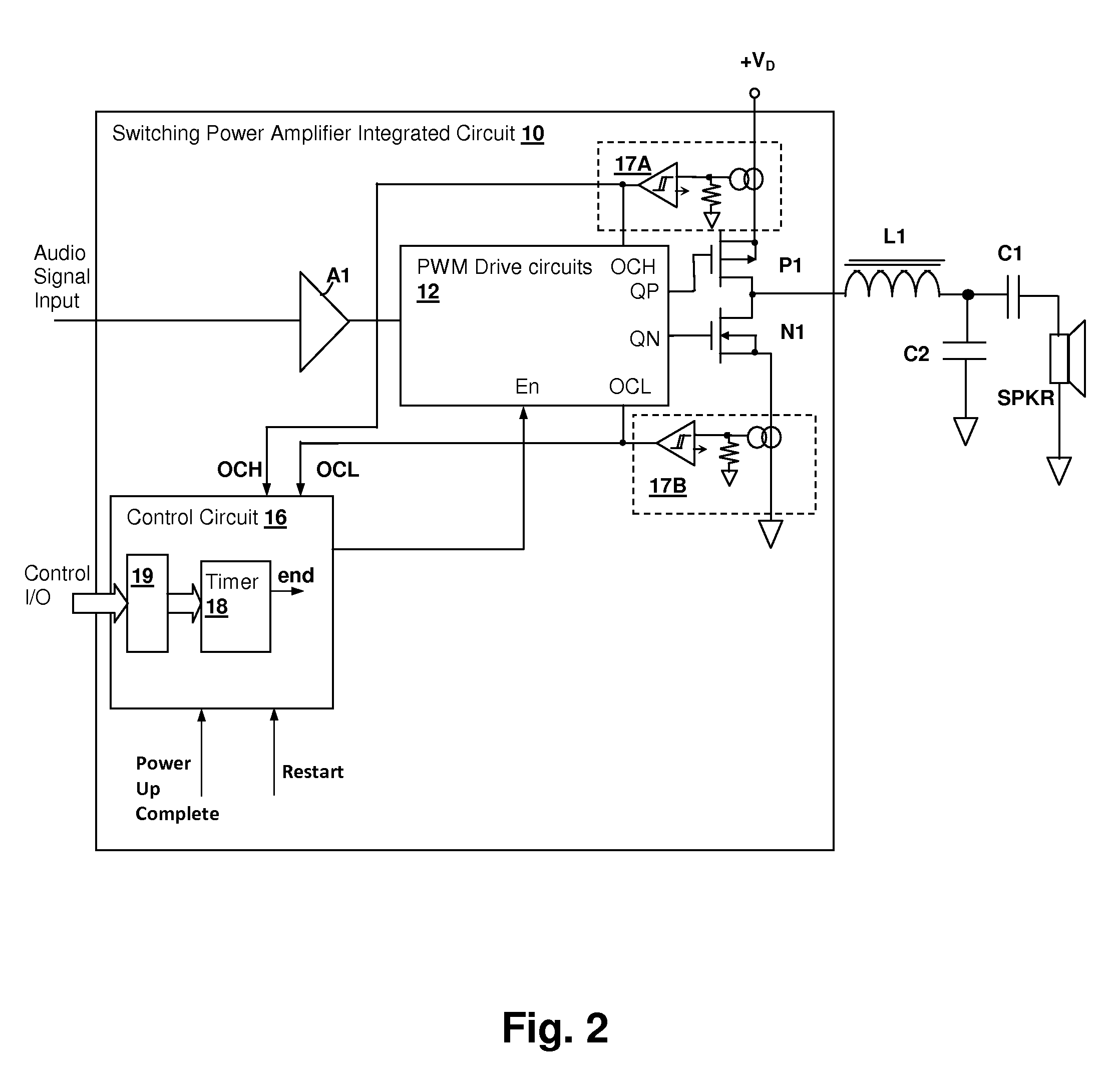
[0022]The present invention encompasses a circuit and method of operation that discharges stored inductive energy from filter inductors and load inductances coupled to the output of a switching power amplifier prior to disabling the switching power stage in response to detection of an over-current condition. The circuit and method thereby prevent latch-up and consequent circuit failure that can be caused by discharge of stored magnetic energy from the inductances into the disabled power stage transistors. The discharging is performed by turning off the transistor(s) of the output stage that conduct current in a direction corresponding to the over-current, and turning on the transistor(s) that have a conduction direction opposing the over-current direction.

[0023]The above-described action immediately interrupts the over-current source, while temporarily maintaining a conduction path for the magnetic energy stored in the load to discharge before the switching power amplifier output st...


PUM


Abstract

An over-current protection circuit protection circuit and method for protecting switching power amplifier circuits provides protection against latch-up and other failures due to energy returned from an inductive load when one or more transistors in the amplifier output are disabled in response to an over-current condition. Upon detection of an over-current condition, the transistor corresponding to the over-current conduction direction is disabled. At the same time, the transistor corresponding to the conduction direction opposite the over-current direction is enabled for a predetermined time period, or until the magnitude of the load current has dropped, so that energy stored in inductance of the load is reduced, preventing back-currents that would otherwise cause latch-up and consequent destruction of the output stage when the switching power output stage is disabled. After the predetermined time period has elapsed or the load current has dropped below a threshold, the entire output stage is disabled.

Description

CROSS-REFERENCE TO RELATED PATENT APPLICATIONS[0001]The present U.S. Patent Application is related to U.S. patent application Ser. No. 11 / 862,324 entitled “PROTECTION CIRCUIT AND METHOD FOR PROTECTING SWITCHING POWER AMPLIFIER CIRCUITS DURING RESET”, filed concurrently herewith, and to U.S. patent application Ser. No. 11 / 862,338 entitled “THERMAL OVERLOAD PROTECTION CIRCUIT AND METHOD FOR PROTECTING SWITCHING POWER AMPLIFIER CIRCUITS” also filed concurrently herewith. Both of the above-referenced U.S. Patent Applications are incorporated herein by reference, have at least one common inventor, and are assigned to the same Assignee.BACKGROUND OF THE INVENTION[0002]1. Field of the Invention[0003]The present invention relates generally to integrated circuit switching power amplifiers, and more specifically, to a circuit and method for protecting against latch-up failures when a switching power amplifier output stage is disabled in response to detection of an over-current condition.[0004...

Claims


Application Information

Patent Timeline
IPC IPC(8): H03F1/52
CPCH03F1/523H03F3/187H03F3/2173
Inventor ZHANG, LINGLIGABORIAU, JOHANN
Owner CIRRUS LOGIC INC
Why Eureka
Try Eureka