Sound detecting mechanism

a technology of sound detection and mechanism, applied in the direction of transducer types, generators/motors, electrical transducers, etc., can solve the problems of poor heat resistance of microphones using such high polymeric organic substances, inability to give reflow treatment, and inability to withstand hea

Inactive Publication Date: 2009-08-04
HOSIDEN CORP +1
View PDF10 Cites 17 Cited by
  • Summary
  • Abstract
  • Description
  • Claims
  • Application Information

AI Technical Summary

Benefits of technology

[0041]With this construction, the signal fetching circuit and the sound detecting mechanism are electrically connected by connection of the bonding technique or the like using metal wires, or by connection of the metal film formed on the substrate in the semiconductor manufacturing process. As a result, miniaturization of the mechanism becomes possible compared with a construction having wires connected by soldering.

Problems solved by technology

The microphone using such a high polymeric organic substance has poor heat resistance, and thus is hardly capable of enduring the heat in time of reflow treatment when mounted on a printed board, for example.
The microphone, therefore, cannot be given reflow treatment when mounted on the printed board or the like.

Method used


Image

  • Sound detecting mechanism
  • Sound detecting mechanism
  • Sound detecting mechanism

Examples


Embodiment Construction

[0042]An embodiment of the present invention will be described hereinafter with reference to the drawings.

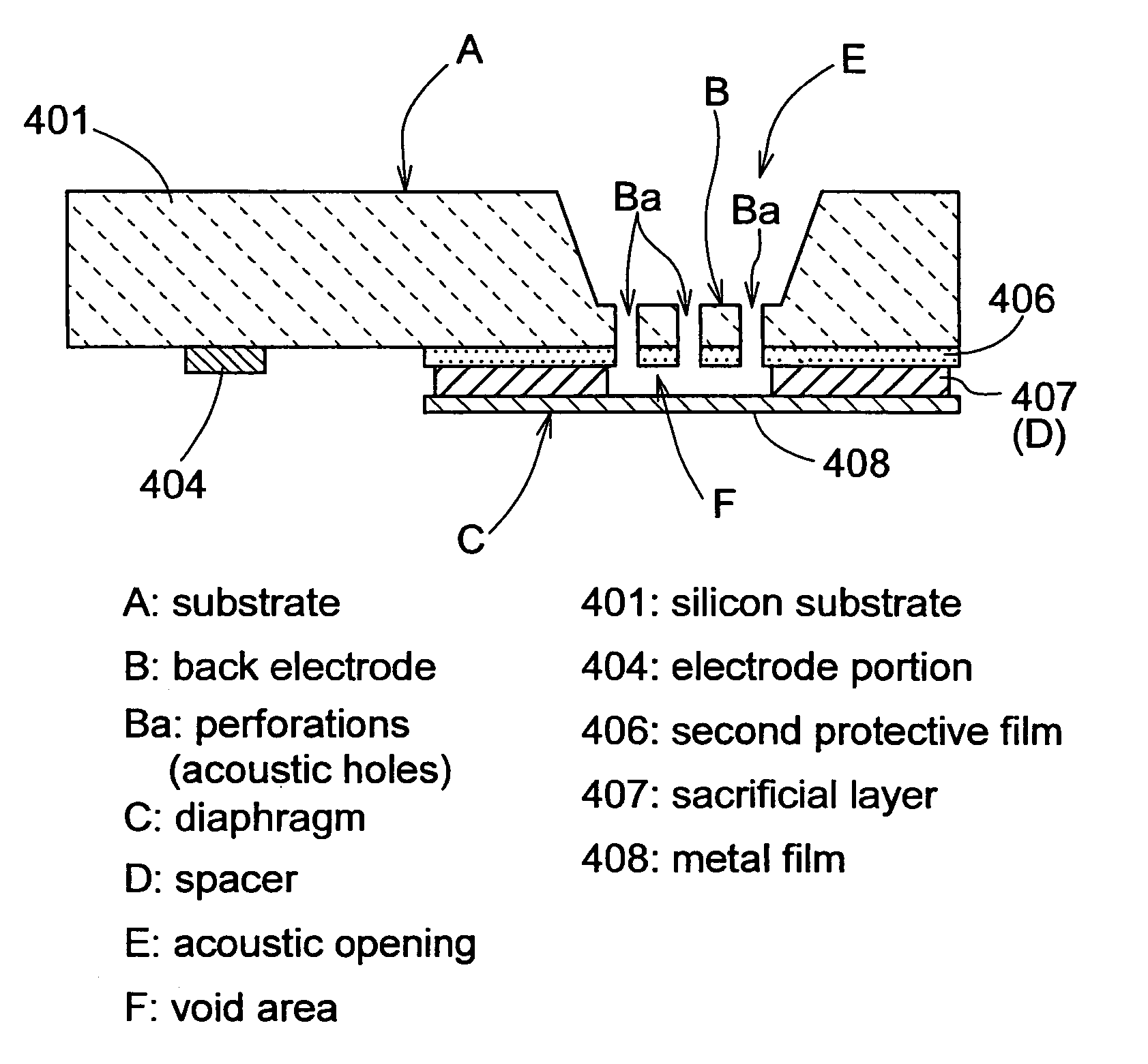
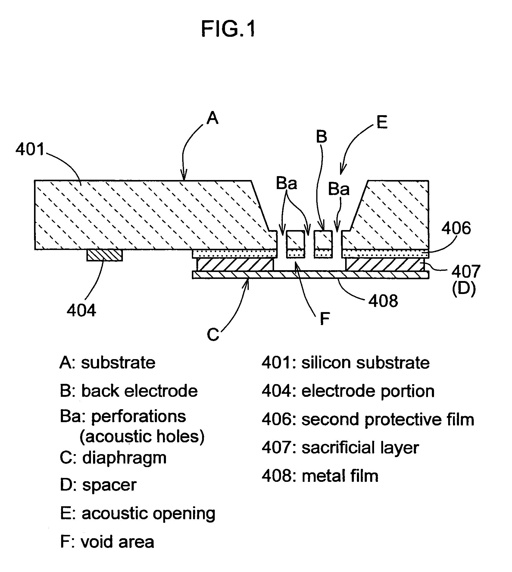
[0043]FIG. 1 is a sectional view of a silicon condenser microphone (simply referred to as a microphone hereinafter) exemplifying a sound detecting mechanism of the present invention. The microphone comprises a monocrystal silicon substrate A having a back electrode B formed in an area thereof, a diaphragm C in the form of a metal thin film opposed to the back electrode B, and a sacrificial layer arranged between the back electrode B and diaphragm C to act as a spacer D. This microphone allows the diaphragm C and the back electrode B to function as a capacitor, which is used to electrically take out variations of capacitance of the capacitor when the diaphragm C is vibrated by sound pressure signals.

[0044]The substrate A in this microphone has a size of a square with one side 5.5 mm in length and around 600 μm in thickness. The diaphragm C has a size of a square with one side 2 m...


PUM


Abstract

A sound detecting mechanism capable of forming a diaphragm and a back electrode on a substrate by a simple process includes acoustic holes corresponding to perforations formed on a front surface of a substrate. A second protective film, a sacrificial layer and a metal film are laminated on the front surface in a portion corresponding to the acoustic holes. The substrate is etched from the back surface thereof to a depth reaching the acoustic holes to form an acoustic opening. Subsequently, by effecting an etching from the back surface of the substrate through the acoustic holes, the sacrificial layer is removed and a void area is formed between the diaphragm made of the metal film, the substrate and the formed perforations. The sacrificial layer that remains after the etching is used as a spacer for maintaining a gap between the back electrode and the diaphragm.

Description

TECHNICAL FIELD[0001]The present invention relates to a sound detecting mechanism comprising a pair of electrodes forming a capacitor on a substrate in which one of the electrodes is a back electrode forming perforations therein corresponding to acoustic holes and the other of the electrodes is a diaphragm. More particularly, the invention relates to a sound detecting mechanism used as a sensor or microphone for measuring sound pressure signals.BACKGROUND ART[0002]Conventionally, condenser microphones are frequently used in mobile phones, for example. A typical construction of condenser microphones is shown in FIG. 7. This condenser microphone comprises a metal capsule 100 including a plurality of perforations “h” corresponding to acoustic holes formed therein, a fixed electrode 300 and a diaphragm 500 provided inside the capsule to be opposed to each other with a spacer 400 therebetween to maintain a predetermined gap, a substrate 600 fixed and fitted to a rear opening of the capsu...

Claims


Application Information

Patent Timeline
Patent Type & Authority Patents(United States)
IPC IPC(8): H04R25/00H04R19/04H04R19/00H04R31/00
CPCH04R19/016H04R19/04
Inventor OHBAYASHI, YOSHIAKIYASUDA, MAMORUSAEKI, SHINICHIKOMAI, MASATSUGUKAGAWA, KENICHI
Owner HOSIDEN CORP
Why Eureka
Try Eureka