
Floating breakwater system and method for dissipating wave energy

a technology of floating breakwater and wave energy, which is applied in the direction of groynes, construction, marine site engineering, etc., can solve the problems of lack of versatility, damage to boats or other craft, erosion of land, etc., and achieve the effect of effective dissipation of wave energy, easy construction, and alleviation of wave destructive natur

Inactive Publication Date: 2009-08-11
HALO MARITIME DEFENSE SYST INC
View PDF25 Cites 28 Cited by
  • Summary
  • Abstract
  • Description
  • Claims
  • Application Information

AI Technical Summary

Benefits of technology

[0007]The purpose of the present invention is to provide an apparatus and system that carries out effective dissipation of the energy of the wave or water motion and which system can be easily constructed in the ocean to alleviate the destructive nature of waves but can also, just as readily, be constructed and installed in a marina, harbor or other location where the movement of the water can be caused by the wake of a boat or normal water movement, including storms that may cause the water to rise to a destructive energy.
[0008]With the present invention, individual modules are provided that are easy and relatively inexpensive to produce and can be made of a plastic material such as polyethylene and molded into the particular desired configuration. A multiplicity of such modules are affixed together in a particular manner and configuration to form the overall floating breakwater system.
[0009]Such system comprises affixing the individual modules together in an aligned vertically disposed panel by means of elastic members such as rubber tubes, thus each vertical panel of modules has a certain flexibility and can flex during its dissipation of the wave or water surge energy. The vertical panels of modules are formed in multiples of such vertically disposed panels and the vertical panels are further joined together to additional similarly constructed vertical panels to create the overall floating breakwater system. Since the vertical panels are also joined together by elastic members, such as rubber tubes, the overall breakwater system can flex both in the vertical as well as horizontal directions, thus providing considerable overall give to the system when a wave or water surge is encountered.

Problems solved by technology

The destructive force at water can, of course, be damaging to structures, cause erosion of land and also damage to boats or other craft that are caused to move by the force of the water motion as it hits other boats or structures.
The problem, therefore, is not limited to shore areas where the erosive effect is potentially damaging to the shore area but can be present in marinas, boat moorage areas or to any structure that abuts or is located in the near proximity to the water.
While often effective, such permanent structures suffer from the lack of versatility, that is, they are permanent, and once constructed, cannot be moved to other locations where such protection is needed.
In addition, there are many locations where permanent structures are simply not appropriate, such as within marinas, harbors or boat channels, where some means to alleviate the potential harm caused by the uncontrolled movement of the water against boats or docks is needed to counter the force of the wakes left by boats as well as the normal motion of the water.

Method used


Image

  • Floating breakwater system and method for dissipating wave energy
  • Floating breakwater system and method for dissipating wave energy
  • Floating breakwater system and method for dissipating wave energy

Examples


Embodiment Construction

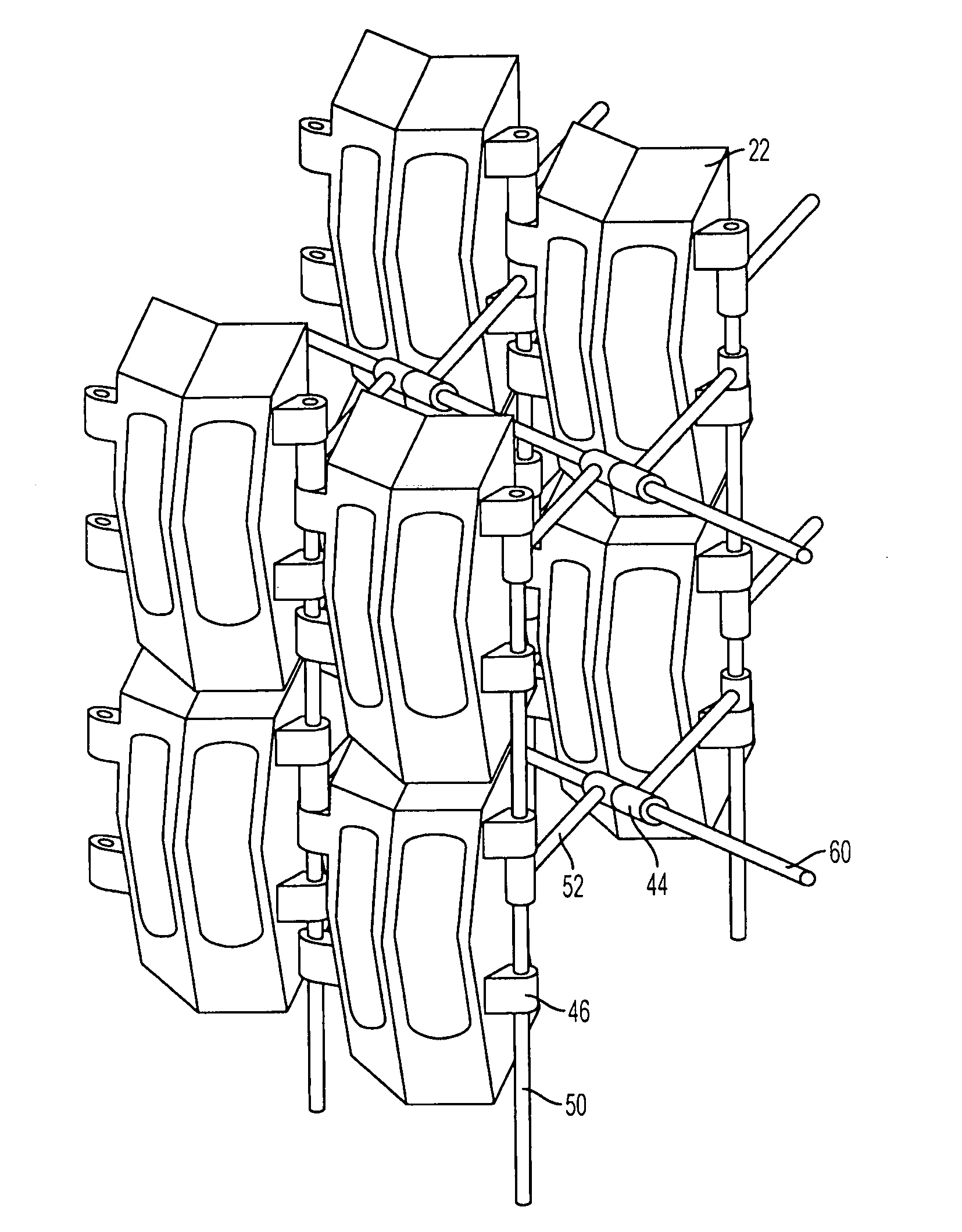
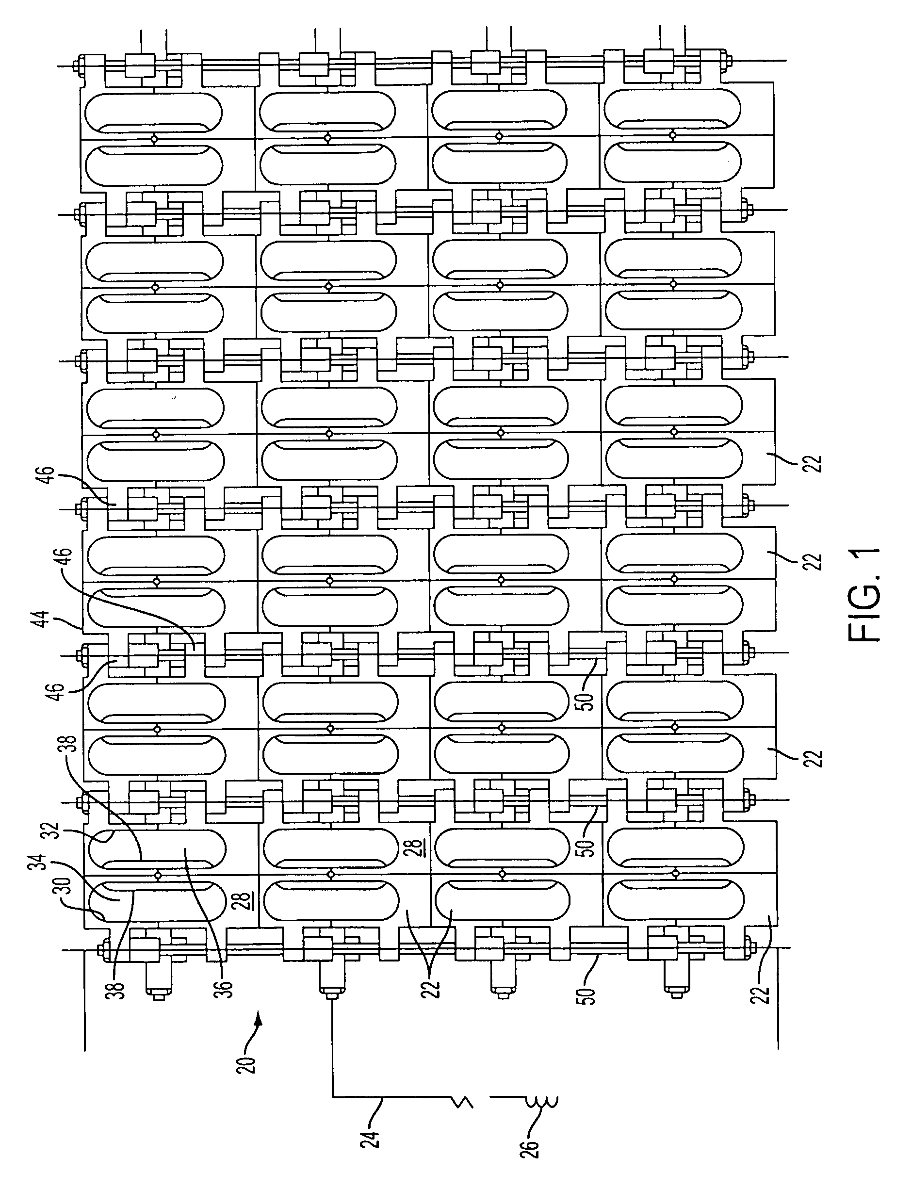
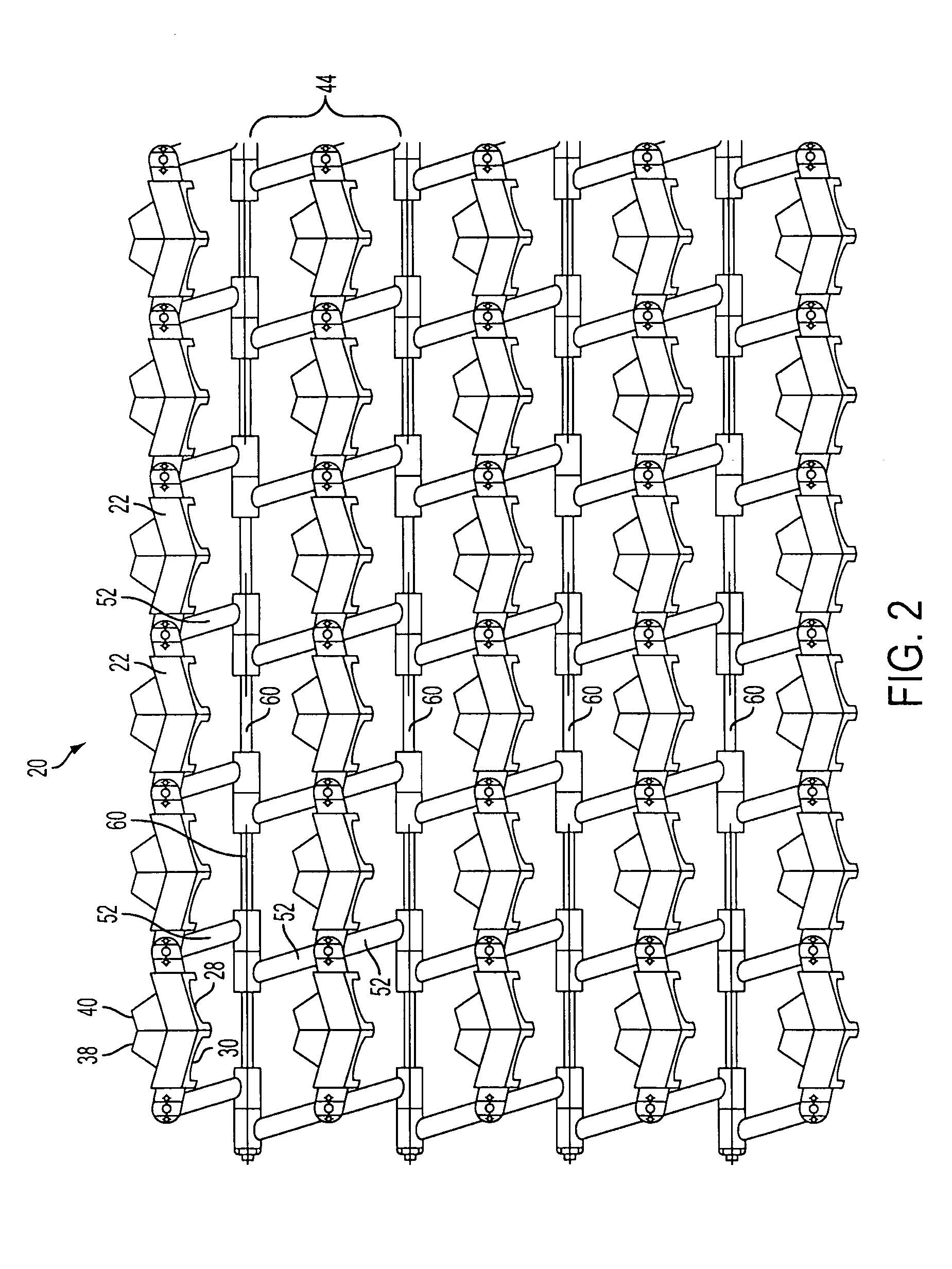
[0037]Referring in particular to FIGS. 1-3, there is shown a floating breakwater system 20 constructed in accordance with the present invention.

[0038]As can be seen, the floatable breakwater system 20 preferably comprises a plurality of modules 22 that are assembled together in order to make up the overall system 20. The system itself is preferably anchored to the bed of the river or sea or the like with flexible cables 24 and anchored by anchor 26, shown schematically in FIG. 1, however, the anchoring of the present breakwater system can be carried out in a similar manner as the anchorage means shown and described in our U.S. Pat. No. 5,879,105. Such sea cables can be SEAFLEX® cables and which are specially adapted to have sufficient strength to bold the system 20 in position but with the necessary elasticity required to maintain the present breakwater system 20 to the bed of the ocean or other body of water. The anchors 26 are also preferably helical anchors that can provide suffi...


PUM


Abstract

A floating breakwater system comprises a plurality of modules that are flexibly affixed together. The modules are affixed together to make up a plurality of vertical panels made up of the modules and the vertical panels themselves are flexibly affixed together in generally parallel relationship. Each individual module has a front face that faces the oncoming wave. There are at least two inlets in the front surface and corresponding outlets in the rear surface and passageways between the inlets and the outlets such that the water propelled by the wave passes through the at least two passageways. Each passageway is tapered inwardly in the direction of the flow of the water and each passageway has a main longitudinal axis. The respective axes are angled inwardly toward each other and converge at a point displaced rearwardly from the outlets so that the water that passes through the passageways intersect at the point and the energy of the wave is dissipated.

Description

BACKGROUND OF THE INVENTION[0001]The present invention relates to an apparatus and a system to carry out the dissipation of the energy of a wave or other like motion at the water and, in particular, to an apparatus and system that can be readily assembled and disassembled on site and which provides protection from the potentially damaging energy of the waves.[0002]The destructive force at water can, of course, be damaging to structures, cause erosion of land and also damage to boats or other craft that are caused to move by the force of the water motion as it hits other boats or structures. The problem, therefore, is not limited to shore areas where the erosive effect is potentially damaging to the shore area but can be present in marinas, boat moorage areas or to any structure that abuts or is located in the near proximity to the water.[0003]There are, of course, numerous types of apparatus that have been proposed and used for the protection of a shoreline against the continual ero...

Claims


Application Information

Patent Timeline
Patent Type & Authority Patents(United States)
IPC IPC(8): E02B3/04E02B3/06
CPCE02B3/062Y02A10/11
Inventor BISHOP, ROBERTBISHOP, JUSTIN
Owner HALO MARITIME DEFENSE SYST INC
Learn More