Copper conductor with anodized aluminum dielectric layer

a technology of anodized aluminum and conductor, which is applied in the direction of insulated conductors, power cables, cables, etc., can solve the problems of low radial dimensional control, inability to meet the requirements of high current density or severe environment applications, and the skin is too thin to electrically insulate the conductor, etc., to achieve the effect of reducing or eliminating internal stresses in materials, facilitating the formation of conductors, and economic viability to produce in large quantities

Active Publication Date: 2009-08-11
FORD GLOBAL TECH LLC
View PDF19 Cites 28 Cited by
  • Summary
  • Abstract
  • Description
  • Claims
  • Application Information

AI Technical Summary

Benefits of technology

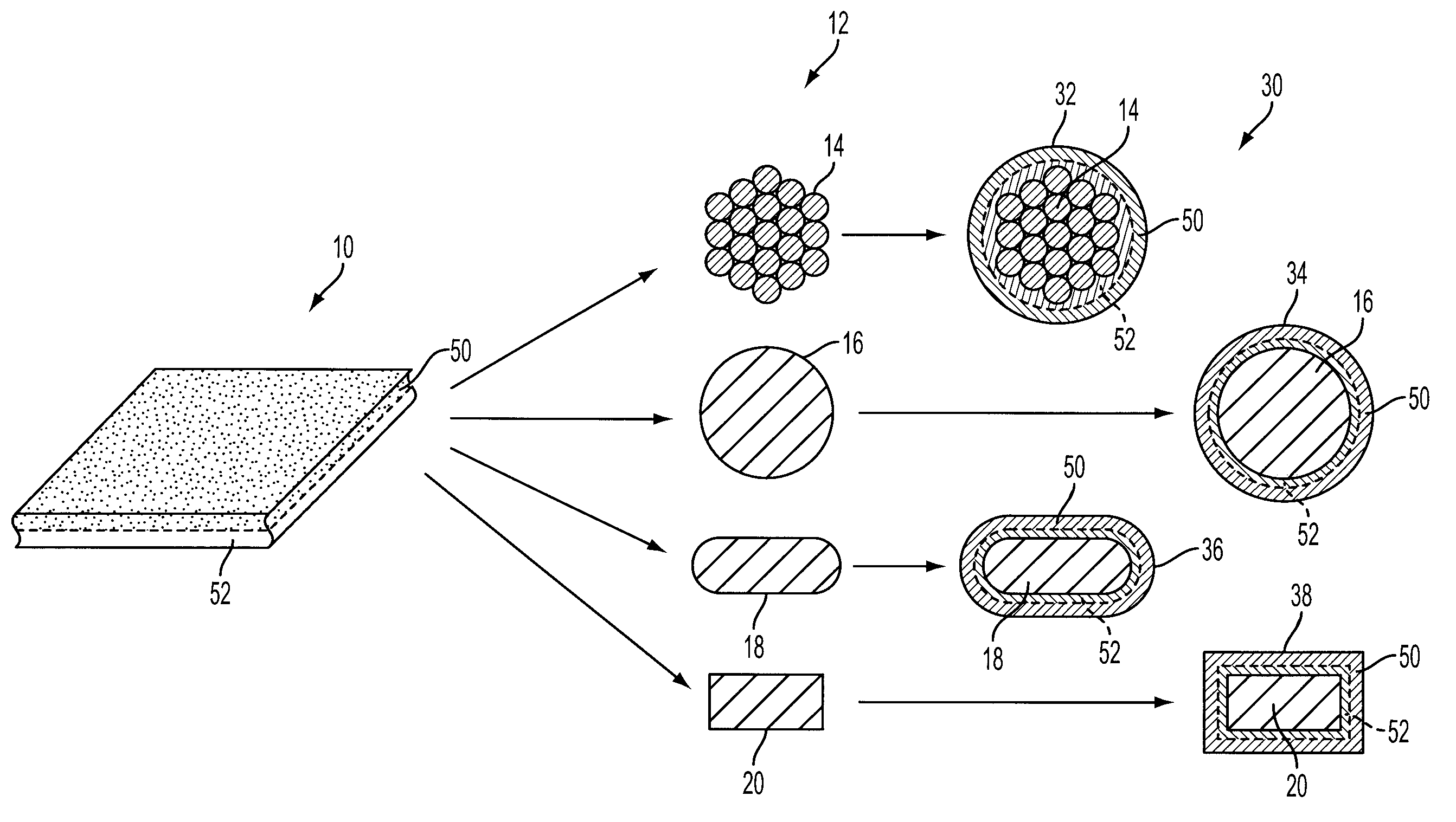
[0009]In one embodiment, a method for forming an insulated electric conductor includes enveloping a copper core with a uniform thickness sheet of aluminum having a thickness of between about 3-15 thousandths inch thick and anodizing the outer surface of the aluminum to form a single dielectric layer of aluminum oxide to electrically insulate the copper core. Anodizing the outer layer of the uniform thickness thin sheet or foil of aluminum may be performed before or after mechanically forming the aluminum to the copper core depending upon the particular application and implementation. The anodizing process may be halted using a suitable rinse to remove the electrolytic agent from the aluminum so that the aluminum sheet is only partially anodized. Controlling the thickness of the aluminum sheet and the anodizing process results in a substantially smooth outer dielectric layer without holes or voids with dielectric / insulating properties proportional to the layer thickness. The method may also include annealing the composite conductor after forming to reduce or eliminate any internal stresses in the materials.
[0010]The present disclosure includes embodiments having various advantages. For example, embodiments of the present disclosure provide an insulated electric conductor that is mechanically tough, chemically resistant, and suitable for operation at extreme operating and / or environmental temperatures hundreds of degrees higher than conventionally insulated wires. The single dielectric / insulating layer is robust against strain-related defects during mechanical forming and economically viable to produce in large quantities and long continuous lengths. In addition, the mechanical toughness facilitates forming conductors of various cross-sectional geometries and gage-diameters. The insulated electric conductor embodiments of the present disclosure have desirable thermal conductivity to dissipate heat and tolerate higher ohmic heating per square while resisting electrical and environmental degradation so the conductor is suitable for use in electromagnetic coil and electric motor applications, for example, and can be wound into volumetric and thermally efficient coils of short total length and improved efficiency. Use of a uniform thickness sheet of aluminum with proper control of the anodizing process results in formation of a single dielectric layer with a substantially smooth outer surface without holes or voids that can be mechanically formed to a solid or stranded copper core.

Problems solved by technology

However, they typically are limited to applications with operating / environmental temperatures below about 200-220° C. and are not suitable for high current density or severe environment applications.
In addition, polymeric coatings are excellent thermal insulators, which is undesirable for dissipation of ohmic or resistance heating in coil windings.
Inorganic wire coverings or coatings, such as glass-fiber sheaths, glass encapsulation, mica, or ceramic materials, may be used to tolerate higher temperatures, but tend to be relatively thick, brittle, and have low radial dimensional control so that they are not amenable to forming processes common in manufacturing electrical machines.
However, this layer or skin is too thin to electrically insulate the conductor, so that other measures are required.
While suitable for some overhead transmission line applications, the bulk resistance of aluminum wire is generally too high for electromagnetic coil and electrical machine applications.
Electroplating aluminum on copper has been attempted, but the aluminum tends to oxidize before it chemically attaches to the copper so that a poor bond is formed and the aluminum layer flakes off of the copper core.
Copper can be plated onto an aluminum conductor core, but does not provide the desired electrical characteristics as described above.
However, the direct anodization of copper as described in these patents is subject to high strain and cracking as shown by the dielectric strength drop described in U.S. Pat. No. 5,501,382, and the coatings of copper are porous, which makes it difficult or impossible to halt the oxidation process, eventually resulting in an electrical short or breakdown of the wire.

Method used


Image

  • Copper conductor with anodized aluminum dielectric layer
  • Copper conductor with anodized aluminum dielectric layer
  • Copper conductor with anodized aluminum dielectric layer

Examples


Embodiment Construction

)

[0016]As those of ordinary skill in the art will understand, various features of the embodiments illustrated and described with reference to any one of the Figures may be combined with features illustrated in one or more other Figures to produce alternative embodiments that are not explicitly illustrated or described. The combinations of features illustrated provide representative embodiments for typical applications. However, various combinations and modifications of the features consistent with the teachings of the present disclosure may be desired for particular applications or implementations.

[0017]For the representative process / product illustrated in FIG. 1, at least one uniform thickness thin sheet of aluminum 10 is formed to envelop a copper or copper alloy core 12, which may be formed in any of a number of geometries including but not limited to generally circular 16, oval or ribbon-shaped 18, or square / rectangular 20. For example, aluminum sheet 10 may be between about 0.0...


PUM

PropertyMeasurementUnit
temperaturesaaaaaaaaaa
thicknessaaaaaaaaaa
thickaaaaaaaaaa

Abstract

An electrically insulated conductor for carrying signals or current includes a solid or stranded copper core of various geometries with only a single electrically insulating and thermally conductive layer of anodized aluminum (aluminum oxide). The device is made by forming a uniform thickness thin sheet or foil of aluminum to envelop the copper or copper alloy core. The aluminum has its outer surface partially anodized either before or after forming to the core in an electrolytic process to form a single layer of aluminum oxide.

Description

BACKGROUND[0001]1. Technical Field[0002]The present disclosure relates to a copper conductor with an anodized aluminum dielectric layer and a method for making the same.[0003]2. Background Art[0004]The general idea of creating an electrically insulating coating layer on a conducting material is well known. For example, organic wire coatings of polyesters, polyimides, thermoset epoxies, silicone rubbers, and many others have been used in a variety of applications for many years. These types of materials have very good dielectric properties and are able to withstand high voltages. However, they typically are limited to applications with operating / environmental temperatures below about 200-220° C. and are not suitable for high current density or severe environment applications. In addition, polymeric coatings are excellent thermal insulators, which is undesirable for dissipation of ohmic or resistance heating in coil windings. Inorganic wire coverings or coatings, such as glass-fiber s...

Claims


Application Information

Patent Timeline
Patent Type & Authority Patents(United States)
IPC IPC(8): H01B7/00
CPCH01B3/105Y10T29/49117H01B9/006
Inventor ELIE, LARRYGINDER, JOHNMARANVILLE, CLAY
Owner FORD GLOBAL TECH LLC
Why Eureka
Try Eureka