Insulated assembly of insulated electric conductors

a technology of insulating electric conductors and assembly, which is applied in the direction of insulating conductors, power cables, cables, etc., can solve the problems of short circuits and related failures, and the limited capacity of polymeric insulation to tolera

Inactive Publication Date: 2011-05-03
FORD GLOBAL TECH LLC
View PDF22 Cites 9 Cited by
  • Summary
  • Abstract
  • Description
  • Claims
  • Application Information

AI Technical Summary

Benefits of technology

[0039]The present disclosure includes embodiments having various advantages. For example, embodiments of the present disclosure provide an insulated assembly of insulated electric conductors that is mechanically tough, chemically resistant, and suitable for operation at extreme operating and / or environmental temperatures hundreds of degrees higher than wire assemblies conventionally insulated with polymeric insulation. The single dielectric / insulating layer is robust against strain-related defects during mechanical forming and is economically viable to produce in large quantities and long continuous lengths. The mechanical toughness facilitates forming conductors of various cross-sectional geometries and gage-diameters.

Problems solved by technology

Conventional wire assemblies having polymeric insulation around copper wires can typically tolerate ohmic (or other) heating of up to approximately 250° C. Once a copper wire heats to temperatures beyond 250° C., the polymeric insulation can break down or melt, thus resulting in short circuits and related failures.
Additionally, polymeric insulation is limited in its capacity to tolerate environmental hazards such as exposure to salt spray and other environmental conditions as are typically encountered by insulation employed in automotive applications.

Method used


Image

  • Insulated assembly of insulated electric conductors
  • Insulated assembly of insulated electric conductors
  • Insulated assembly of insulated electric conductors

Examples


first embodiment

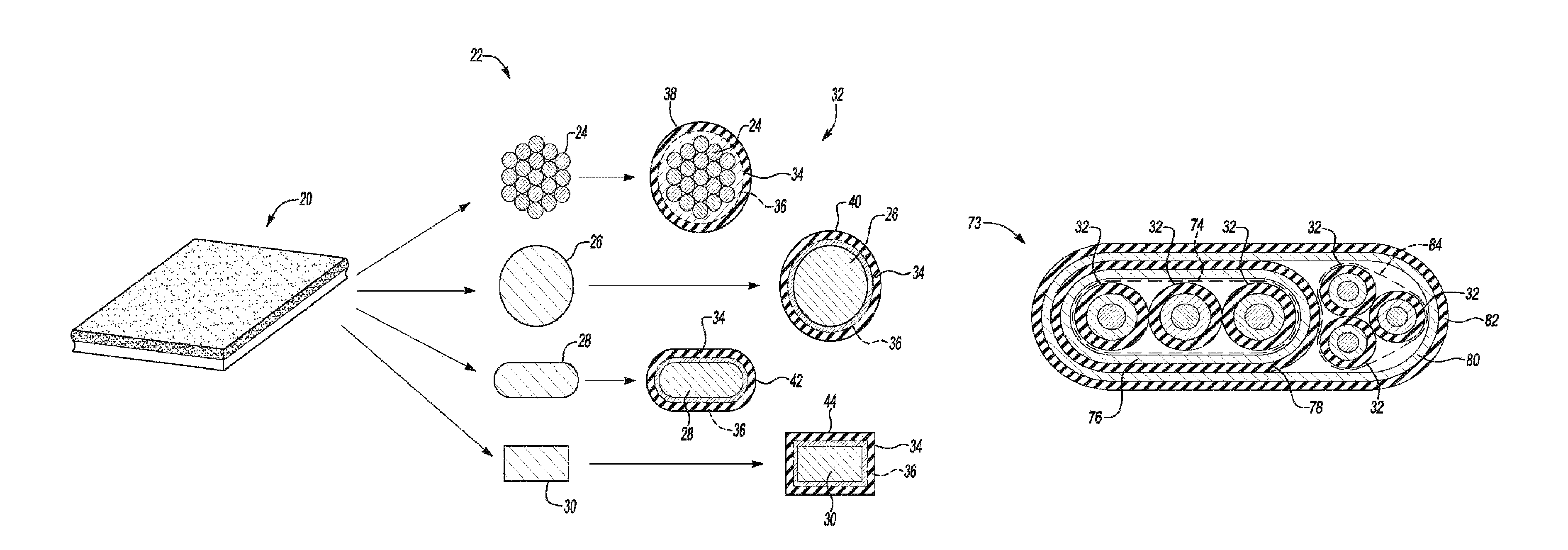
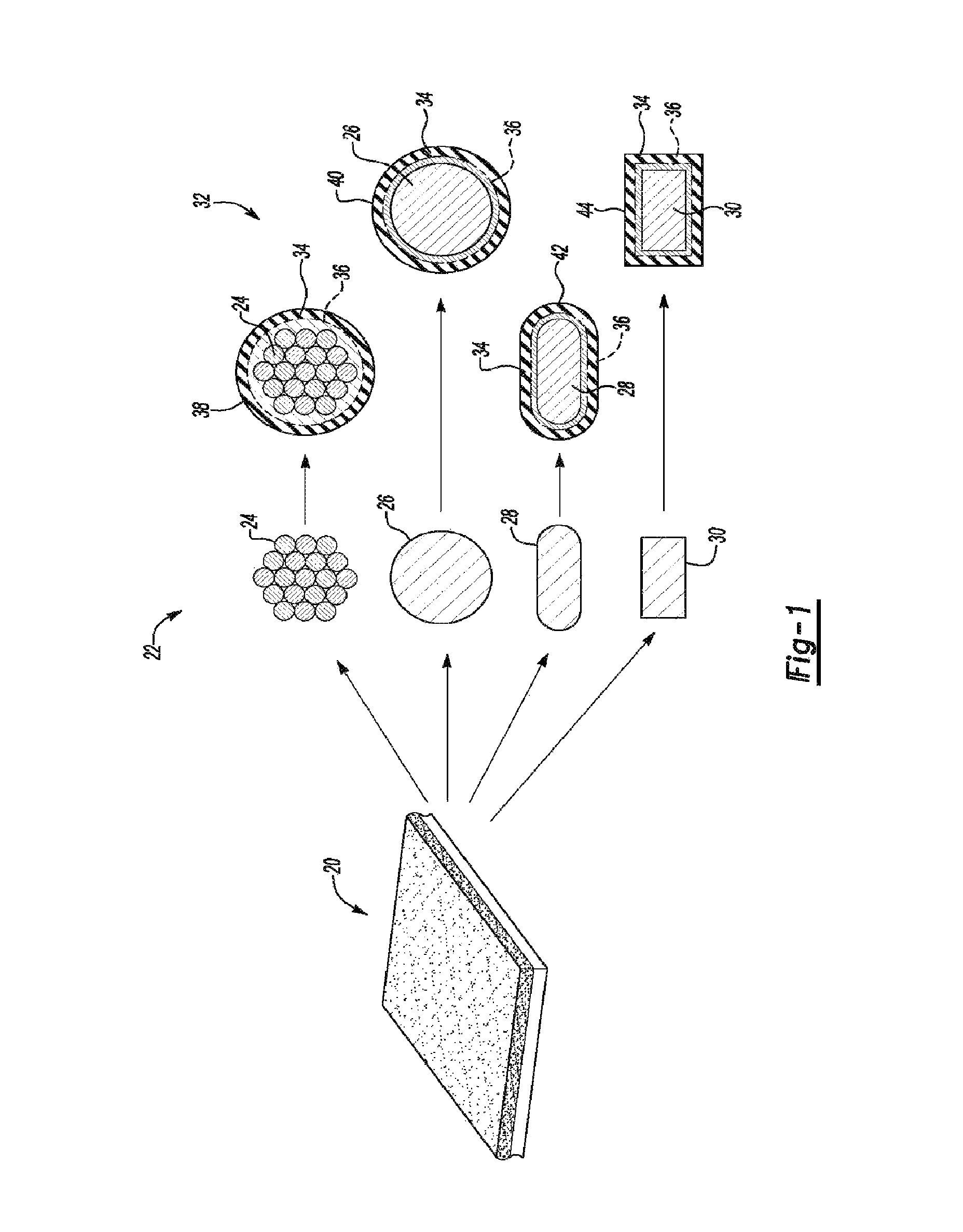
[0050]With respect to FIG. 3, an insulated assembly of insulated conductors 73 including three insulated electric conductors 32 is schematically illustrated in cross section. Electric conductors 32 are disposed proximate one another in a line abreast configuration to form a first plurality 74 of insulated conductors. In other implementations, the insulated electric conductors 32 may be positioned in a triangular orientation. In other implementations, only two insulated electric conductors 32 may be employed while in still other implementations, greater than three insulated electric conductors 32 may be employed and disposed in various different geometric configurations. Additionally, it should be understood that although cores 22 having a circular cross section have been depicted, individual cores 22 having any desirable cross section geometry may be utilized.

[0051]The first plurality of insulated conductors 74 is surrounded by a first aluminum layer 76 which has been mechanically f...

second embodiment

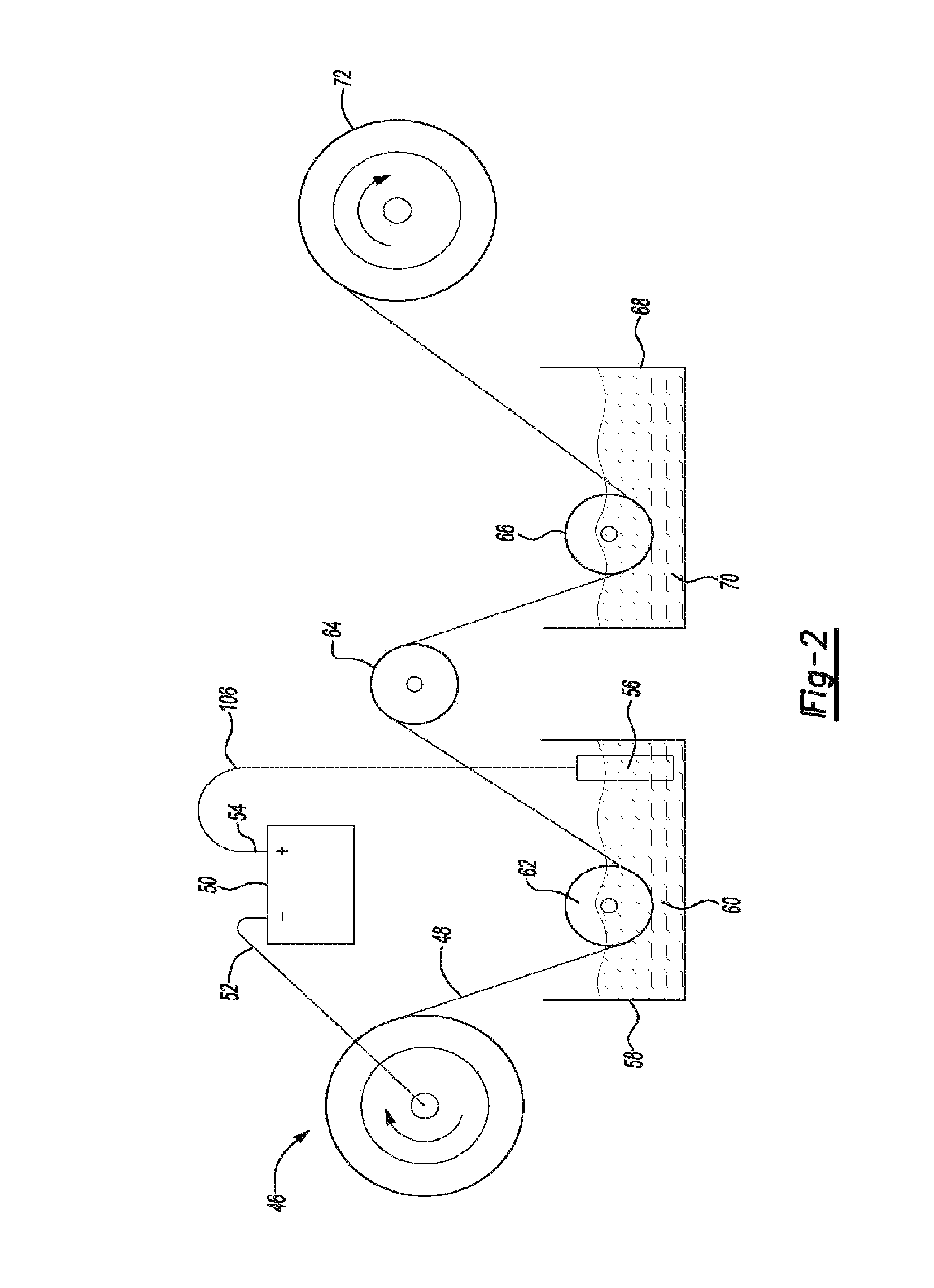
[0059]With respect to FIGS. 10 through 15, the present invention is illustrated. With respect to FIG. 10, insulated assembly of insulated conductors 73A includes a first plurality 74A of insulated conductors 32 surrounded by a first single dielectric layer of aluminum oxide 78A. In this embodiment, the first plurality of insulated conductors 74A was first surrounded by a uniform thickness thin sheet of aluminum 20 and then subjected to the electrolytic process described above with respect to FIG. 2 for a prolonged period of time until all of the aluminum in uniform thickness thin sheet of aluminum 20 was oxidized to form first single dielectric layer of aluminum oxide 78A. Alternatively, other methods of completely oxidizing the uniform thickness thin sheet of aluminum 20 may be employed.

[0060]With respect to the implementations depicted in FIGS. 11-15, these implementations depict configurations similar to those described above. For instance, the configuration depicted in FIG. 11 c...


PUM

PropertyMeasurementUnit
temperaturesaaaaaaaaaa
thicknessesaaaaaaaaaa

Abstract

An insulated assembly of insulated electric conductors includes a first plurality of insulated electric conductors. Each insulated electric conductor has a copper core, a uniform thickness thin sheet of aluminum that is mechanically formed to envelope the copper core and a single dielectric layer of aluminum oxide that is formed by anodizing an outer surface of the thin sheet of aluminum. A first aluminum layer is mechanically formed to envelope the first plurality of insulated electric conductors and a first single dielectric layer of aluminum oxide surrounds the first aluminum layer.

Description

BACKGROUND OF THE INVENTION[0001]1. Field of the Invention[0002]The present disclosure relates to an insulated assembly of insulated electric conductors wherein each conductor is individually insulated in an anodized aluminum dielectric layer, bundled together in various configurations, and then the bundled configurations are insulated in an anodized aluminum dielectric layer.[0003]2. Background Art[0004]In U.S. Pat. No. 7,572,980, a single stranded copper conductor with an anodized aluminum dielectric layer was disclosed. That application described an insulated electric conductor for carrying signals or current having a copper core of various geometries with a single thermally conductive dielectric layer of anodized aluminum (aluminum oxide). That application is incorporated herein by reference.[0005]Conventional wire assemblies having polymeric insulation around copper wires can typically tolerate ohmic (or other) heating of up to approximately 250° C. Once a copper wire heats to ...

Claims


Application Information

Patent Timeline
Patent Type & Authority Patents(United States)
IPC IPC(8): H01B7/00
CPCH01B3/105Y10T29/49117H01B9/006
Inventor ELIE, LARRY DEANGALE, ALLAN ROYGINDER, JOHN MATTHEWMARANVILLE, CLAY WESLEY
Owner FORD GLOBAL TECH LLC
Why Eureka
Try Eureka