Lens driving apparatus, imaging apparatus, and lens barrel and camera main body used for this

a driving apparatus and lens barrel technology, applied in the field of imaging apparatus, can solve the problems of difficult to achieve suitable performance for realizing high-quality images, disadvantageous in terms of compact size and cost, and difficult to realize compact lens barrel and low cost, and achieve smooth origin detection and precise alignment control. , the effect of low cos

Inactive Publication Date: 2009-08-11
PANASONIC CORP
View PDF23 Cites 27 Cited by
  • Summary
  • Abstract
  • Description
  • Claims
  • Application Information

AI Technical Summary

Benefits of technology

[0041]The present invention is for solving the above-stated conventional problems, and it is an object of the present invention to provide a lens driving apparatus that prevents the generation of a detection error of the origin without impairing the compact size, to realize a compact lens barrel at a low cost in an imaging apparatus, and further to provide an imaging apparatus and a lens driving apparatus capable of smooth origin detection and precise alignment control.

Problems solved by technology

However, in the conventional lens driving apparatus like FIG. 58, the positional relationship between the photo-interruption member attached to the lens unit and the photosensor differs in absolute position for each detection operation because of errors in looseness of the lens unit in the driving direction and variations in mechanism and electrical properties due to temperature and humidity changes in the operation environment, thus making it difficult to obtain suitable performance for realizing a high quality image, etc.
This method is advantageous for enhancing the detection accuracy of the absolute position, but is disadvantageous in terms of compact size and cost.
Therefore, in an interchangeable lens type imaging apparatus, it is difficult to realize a compact lens barrel and a low cost.
Further, there is a variation in focus position because of errors of variations in mechanism and electrical properties due to a temperature and humidity change in the operation environment of the lens barrel, thus making it difficult to obtain sufficient performance.
This becomes a factor of limiting downsizing in the optical axis direction and its orthogonal direction, which means an obstacle to downsizing of the lens barrel.
Further, in the origin detection method shown in FIG. 60, the following problems occur in the case of abnormal completion.
The abnormal completion refers to the completion caused by a decrease in voltage because the battery for supplying to the imaging device becomes exhausted or careless detachment of a connection terminal to an external power supply during an operation using the external power supply, for example.
In this case, if the light of the photosensor is interrupted by the photo-interruption member of the focus lens unit because of a decrease in voltage, the process for detecting the origin cannot be performed normally and a malfunction will occur.
In this way, the conventional example having a photosensor used common to the zoom lens unit and the focus lens unit has several problems.
Further, the focus adjustment apparatus described in Patent Document 4 requires the configuration such as a photosensor separately provided to detect the origin of the stepping motor, thus having a problem of being incapable of achieving the downsizing of the imaging apparatus.
Therefore, there is a problem that an error occurs when the shifting amount from the origin is specified from the pulse number applied to the stepping motor.

Method used


Image

  • Lens driving apparatus, imaging apparatus, and lens barrel and camera main body used for this
  • Lens driving apparatus, imaging apparatus, and lens barrel and camera main body used for this
  • Lens driving apparatus, imaging apparatus, and lens barrel and camera main body used for this

Examples


embodiment 1

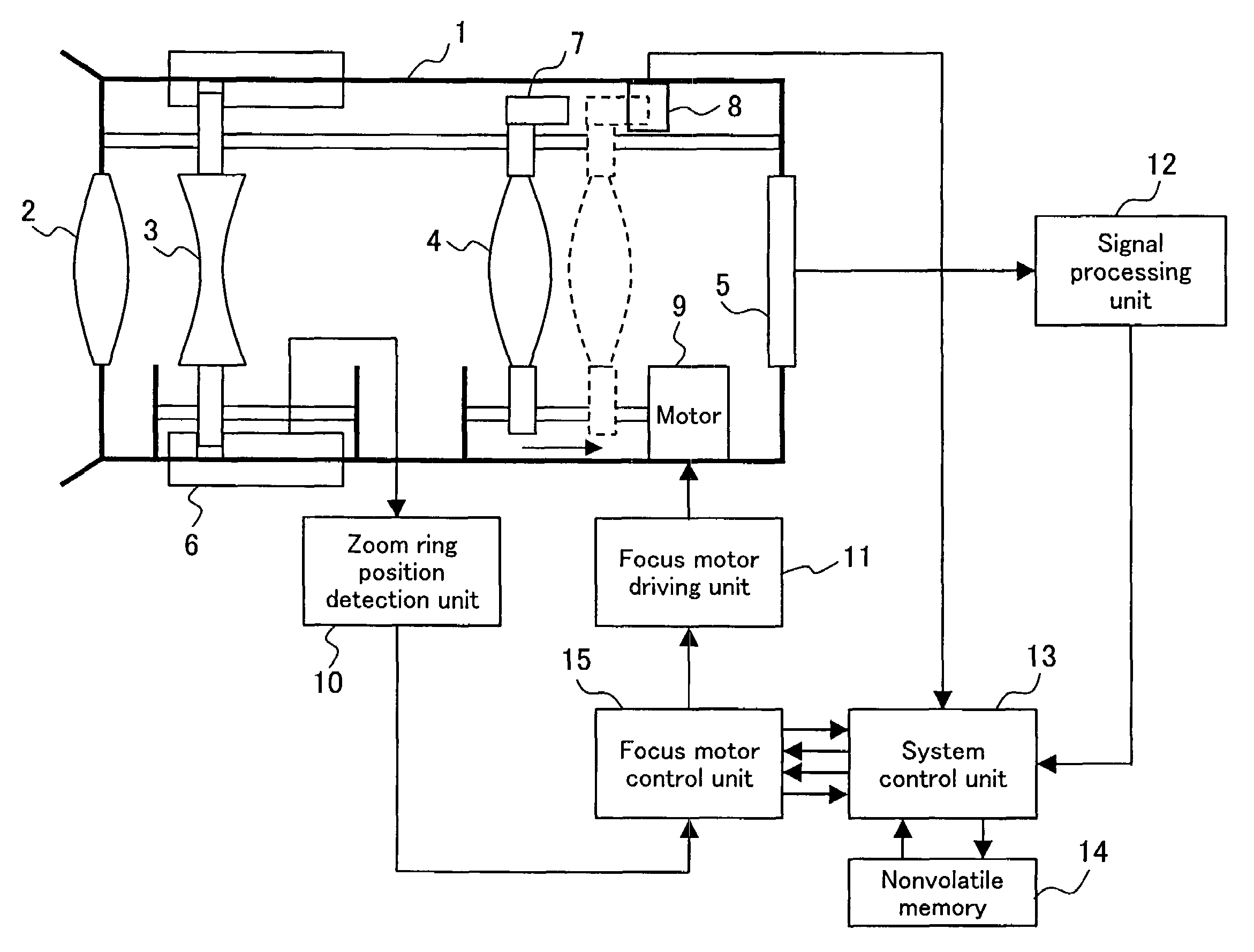
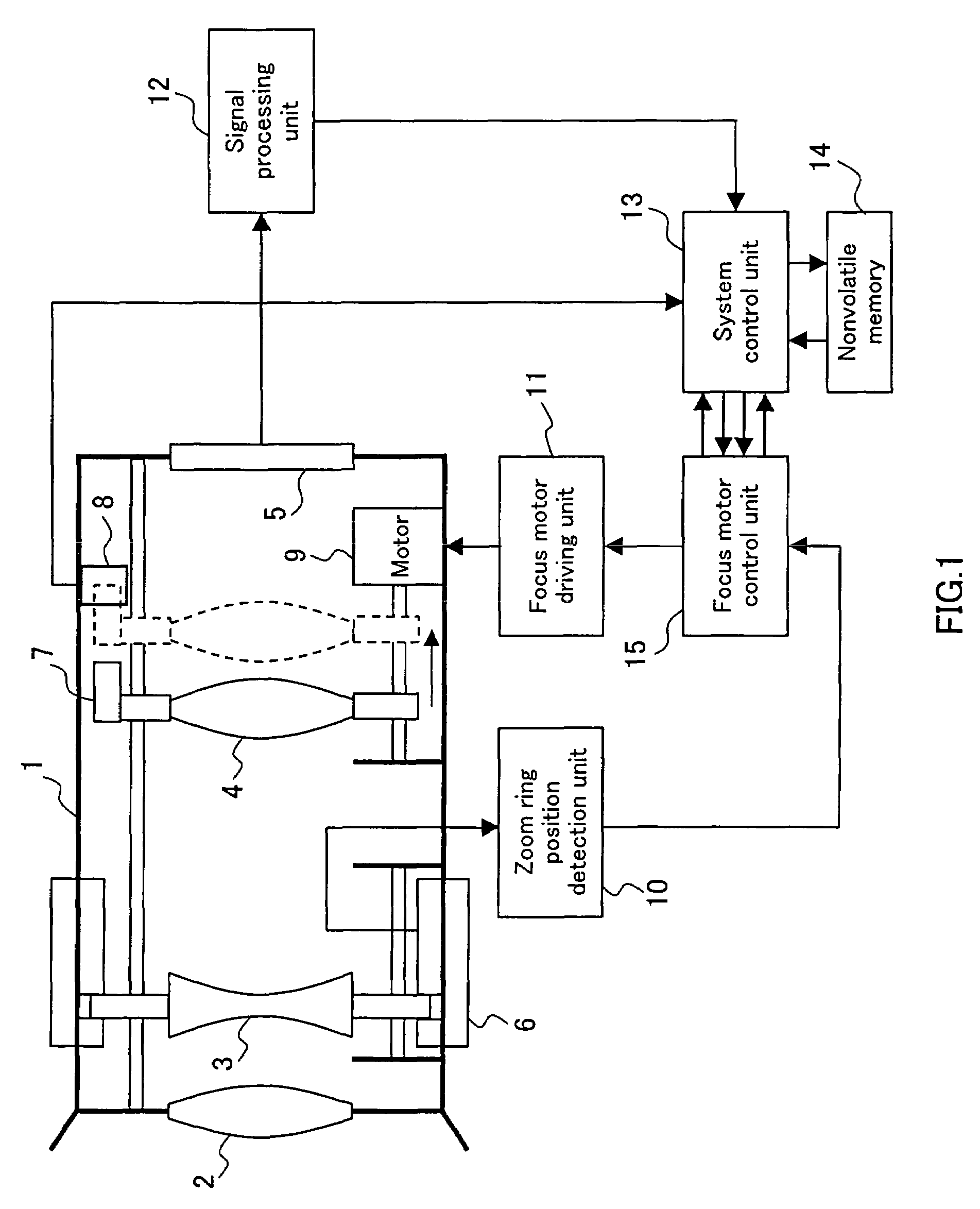
[0177]FIG. 1 includes a schematic diagram and a block diagram of a lens driving apparatus according to Embodiment 1 of the present invention. In FIG. 1, numeral 1 denotes a lens barrel, 2 denotes a fixed lens fixed to the lens barrel 1 and 3 denotes a zoom lens. The zoom lens 3 moves in the optical axis direction so as to adjust a zoom magnification along with the rotation of a zoom ring 6 along the perimeter of the lens barrel 1. Numeral 4 denotes a focus lens. When a motor 9 as a driver rotates, the focus lens 4 moves in the optical axis direction along a lead screw with threads cut therein so as to enable the adjustment of focus.

[0178]In the example of FIG. 1, the motor 9 is a stepping motor that rotates in accordance with a phase of a driving signal (exciting signal) for a motor coil output from a focus motor driving unit 11. Numeral 5 denotes an imaging device that converts an image of a subject captured through the fixed lens 2, the zoom lens 3 and the focus lens 4 into an ele...

embodiment 2

[0214]The following describes Embodiment 2 of the present invention. Embodiment 2 is the same as in Embodiment 1 in the configuration shown in FIG. 1 and FIG. 2 and the origin detection operation during the process adjustment described referring to FIG. 3 and FIG. 4.

[0215]Referring now to FIGS. 8 and 9, the origin detection operation of a focus lens 4 during the normal operation in Embodiment 2 is described below. FIG. 8 is a drawing for explaining the origin detection operation during the normal operation according to Embodiment 2. Since the exciting position, the A-phase current, the B-phase current, the absolute position counter and the photosensor output level shown in FIG. 8 are the same as those described in FIG. 3, the duplicate explanations are omitted.

[0216]Embodiment 2 is different from Embodiment 1 in that the exciting position is decreased by two at one time when the focus lens 4 is shifted to the imaging device 5 side. Therefore, an absolute position counter 153, which ...

embodiment 3

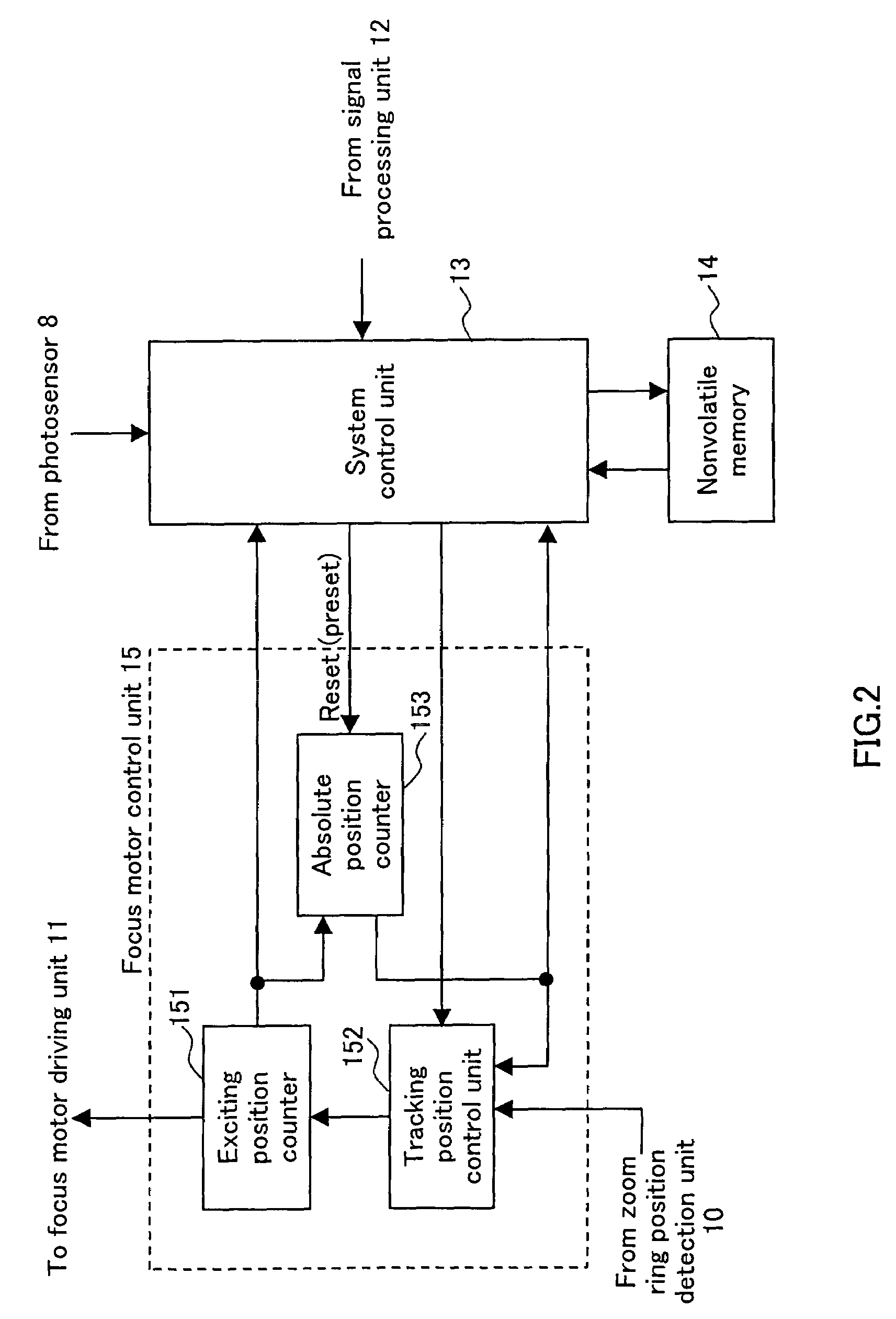
[0226]The following describes Embodiment 3 of the present invention. In the following description, duplication of the configurations shown in FIG. 1 and FIG. 2 described in Embodiment 1 is omitted. Embodiment 3 explains the example where the focus motor driving unit 11 of FIG. 1 drives the motor 9 to rotate by substantially sine wave driving (called also microstep driving). Further, the exciting position counter 151 of FIG. 2 is a 5-bit counter that comes full circle with the counter value of 32 representing one cycle (360 degrees) of the driving electrical angle of the motor 9. The absolute position counter 153 operates in synchronization with the counter value of the exciting position counter 151, and is preset or reset under a predetermined condition described later.

[0227]The operation is described below, with reference to FIG. 10. FIG. 10 is a drawing for explaining an origin detection operation during the process adjustment according to Embodiment 3. The “exciting position” sho...


PUM


Abstract

A lens position calculator is provided that determines a phase of a driving signal as a reference position of an imaging lens when an output value of a position detection sensor reaches a threshold value. The lens position calculator determines a position obtained by performing addition or subtraction on the reference position read out from a reference position storage as a judgment position, detects an output value of the position detection sensor at a timing in synchronization with the driving signal that drives a driver and at the judgment position, and judges whether the output value of the position detection sensor at the judgment position reaches the threshold value or not, so as to determine the reference position again.

Description

TECHNICAL FIELD[0001]The present invention relates to an imaging apparatus such as a still camera or a video movie, a lens driving apparatus that controls a position of a lens of such an apparatus and relates to a lens barrel and a camera main body used for an imaging apparatus.BACKGROUND ART[0002]Conventionally, a method for detecting the origin of a lens unit is proposed in which when the lens unit is driven by a motor, a photo-interruption member attached to the lens unit and a photosensor are used so as to monitor an output level of the photosensor at the time when the photo-interruption member transverses the photosensor (Patent Document 1, for example).[0003]A conventional lens driving apparatus is described below, with reference to FIG. 58. FIG. 58 includes a schematic diagram and a block diagram of an exemplary conventional lens driving apparatus. In an imaging device 75, an image of a subject captured through a fixed lens 72 fixed to a barrel 71, a zoom lens 73 and a focus ...

Claims


Application Information

Patent Timeline
Patent Type & Authority Patents(United States)
IPC IPC(8): G03B13/00G02B7/08G02B7/10G02B7/36G03B17/56G03B21/58
CPCG02B7/08G02B7/102G03B21/58G03B17/56G02B7/36G03B3/10
Inventor HONJO, KENICHISHIBUNO, KOUJIHAYASHI, TAKAYUKIMURAYAMA, MASATO
Owner PANASONIC CORP
Why Eureka
Try Eureka