
Blood treatment catheter assembly

a catheter and blood technology, applied in the direction of multi-lumen catheters, catheters, other medical devices, etc., can solve the problem that cannot be readily inserted into the vascular system of patients, and achieve the effect of avoiding rough transitions

Inactive Publication Date: 2009-08-18
ANGIODYNAMICS INC
View PDF22 Cites 41 Cited by
  • Summary
  • Abstract
  • Description
  • Claims
  • Application Information

AI Technical Summary

Benefits of technology

[0020]The end of the withdrawal tube is preferably beveled so that little or none of the stiffening tube is exposed. The profile presented by the assembly of the catheter and stiffening tube is minimal and relatively smooth in that it avoids rough transitions.
[0022]In a presently preferred embodiment, the unitary housing has a circular cross-sectional periphery and the two lumens are substantially semi-circular in cross-section. In order to maintain this circular catheter profile, the lumens remain substantially semi-circular over most of the length of the unjoined tubes as well as the entire length of the joined tubes that are in the unitary housing. However, the portion of the longer tube that extends past the shorter tube preferably transitions to a circular profile with a circular lumen so as to effectively engage the stiffening tube.

Problems solved by technology

These tubes are made of a highly flexible material that tends to accordian so that by themselves they cannot readily be inserted into a patient's vascular system.

Method used


Image

  • Blood treatment catheter assembly
  • Blood treatment catheter assembly
  • Blood treatment catheter assembly

Examples


Embodiment Construction

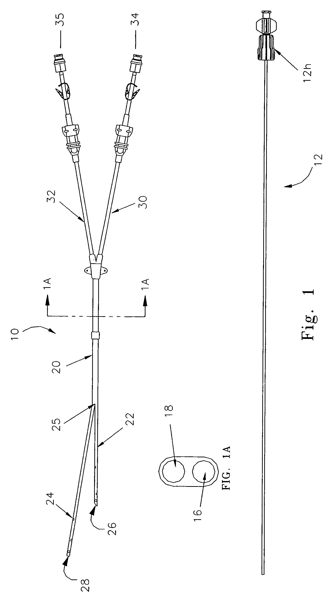
[0034]FIGS. 1-5 illustrate an embodiment of the invention.

[0035]A dual-lumen split tip catheter 10 containing a stiffening tube 12 is shown unassembled in FIG. 1 and assembled in FIG. 2. The stiffening tube 12, which has been called an obturator, is generally a hollow cannula made of a plastic material such as polytetrafluoroethylene, also known as PTFE resin, sold under the trademark Teflon (PTFE resin) made by DuPont of Wilmington, Del. It is to be understood, however, that the stiffening tube 12 can be any longitudinal stiffening member, hollow or not, which performs the function described herein.

[0036]The stiffening tube 12 has a standard luer hub 12h at the proximal end of the device for connection to the catheter 10. The catheter 10 is comprised of a withdrawal lumen 16 and a supply lumen 18.

[0037]The withdrawal lumen 16 is the shorter lumen. It is contained within a proximal tube 30, a joined segment 20 and a distal split tube segment 22 and terminates at a distal port 26.

[00...


PUM


Abstract

A blood treatment catheter pre-assembled with a stiffening tube is provided. The catheter includes a withdrawal lumen and a supply lumen each having distal split tube unjoined segments and an intermediate joined segment. The split tube segment of the supply lumen is provided with a sidewall aperture. The stiffening tube extends through the withdrawal split tip tube, out the distal end of the withdrawal tube, through the aperture of the supply split tip tube and through the split tip supply tube distal of the aperture, out the distal end of the split tip supply tube. When the stiffening tube is positioned inside the catheter, the aperture is adjacent to the withdrawal tube distal opening so as to minimize stiffening tube exposure and to provide a smooth exterior profile. In a preferred design, the tubes and their lumens, over their common length, are semi-circular to provide a circular profile for the catheter.

Description

REFERENCE TO RELATED APPLICATIONS[0001]This application is a continuation-in-part and claims the priority benefit of U.S. patent application Ser. No. 10 / 331,667 filed Dec. 27, 2002 entitled now U.S. Pat. No. 6,966,886: Blood Treatment Catheter Assembly and U.S. Provisional Application No. 60 / 427,831 filed Nov. 20, 2002; which is entitled: Split-Tip Catheter Insertion Apparatus, claim to priority of the Provisional Application having been made in application Ser. No. 10 / 331,667.FIELD OF THE INVENTION[0002]The present invention relates to a blood treatment catheter assembly and more particularly to a split tip, dual-tube hemodialysis catheter having enhanced ease of placement.BACKGROUND OF THE INVENTION[0003]Hemodialysis is a blood treatment procedure for patients with renal failure or in other cases where the kidneys cannot adequately cleanse the blood of toxins. During hemodialysis, the patient's blood is withdrawn, filtered of toxins, and returned to the blood stream. The dialysis ...

Claims


Application Information

Patent Timeline
Patent Type & Authority Patents(United States)
IPC IPC(8): A61M37/00A61M25/00A61M3/00A61M5/178
CPCA61M25/0068A61M1/3661A61M25/007A61M2025/0031A61M2025/0037A61M2025/0188A61M2025/0034
Inventor APPLING, WILLIAM M.
Owner ANGIODYNAMICS INC
Learn More