Methods and systems for combustion dynamics reduction

a technology of combustion dynamics and reduction methods, applied in the field of gas turbine engines, can solve the problems of large amplitude pressure oscillation, unacceptably high nitrogen oxide pollutants in the type of combustion chamber, and inability to reduce the sensitivity of fuel composition, so as to reduce the sensitivity to fuel composition

Active Publication Date: 2009-08-25
GENERAL ELECTRIC CO
View PDF20 Cites 71 Cited by
  • Summary
  • Abstract
  • Description
  • Claims
  • Application Information

AI Technical Summary

Problems solved by technology

However, as a result of the high temperatures involved during combustion, this type of combustion chamber may produce unacceptably high levels of nitrogen oxide pollutants called NOX.
While lean premixed combustion has demonstrated significant reduction in NOx emissions, LPM combustion may suffer from combustion instabilities due to the lean nature of the fuel flow in that operating range.
These pressure fluctuations excite the acoustic modes of the combustion chamber resulting in large amplitude pressure oscillations.
This may result in an oscillatory delivery of fuel to the combustion chamber.
When the oscillating fuel-air mixture burns in the combustion chamber, the flame area fluctuates giving rise to heat release oscillations.
Depending upon the relative phasing of these heat release oscillations and the acoustic waves, a potentially self-exciting feedback loop may be created giving rise to oscillations whose amplitude grows with time.
Such combustion driven instabilities have adverse effect on the system performance and operating life of the combustion chamber.
The oscillations and their resultant structural vibrations can cause fretting and wearing at the walls of the combustion chamber, reducing high cycle fatigue life and affecting the overall performance.

Method used


Image

  • Methods and systems for combustion dynamics reduction
  • Methods and systems for combustion dynamics reduction
  • Methods and systems for combustion dynamics reduction

Examples


Embodiment Construction

[0018]Example embodiments of the invention now will be described more fully hereinafter with reference to the accompanying drawings, in which some, but not all embodiments are shown. Indeed, the invention may be embodied in many different forms and should not be construed as limited to the embodiments set forth herein; rather, these embodiments are provided so that this disclosure will satisfy applicable legal requirements. Like numbers refer to like elements throughout.

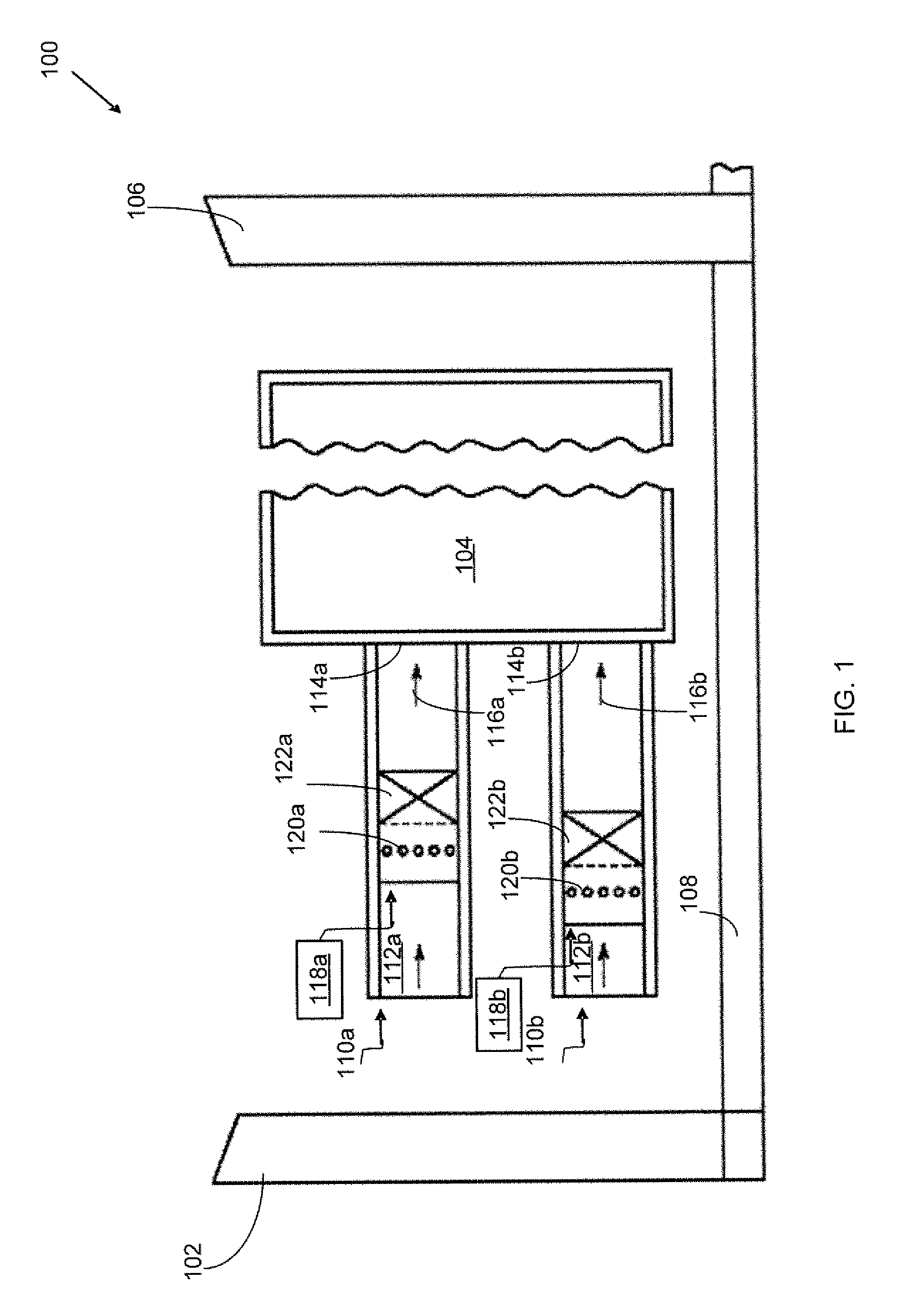
[0019]FIG. 1 is a schematic representation of a portion of an example gas turbine engine 100 according to one embodiment of the invention. The gas turbine engine 100 may include a low NOX combustion chamber 104. The engine 100 may also include a compressor 102, which is in a serial flow communication with the low NOX combustion chamber 104 and a turbine 106. The turbine 106 may be coupled to the compressor 102 through a shaft 108. The shaft 108 may be extended to power an external load (not shown in figure) by the tu...


PUM


Abstract

Methods and systems for combustion dynamics reduction are provided. A combustion chamber may include a first premixer and a second premixer. Each premixer may include at least one fuel injector, at least one air inlet duct, and at least one vane pack for at least partially mixing the air from the air inlet duct or ducts and fuel from the fuel injector or injectors. Each vane pack may include a plurality of fuel orifices through which at least a portion of the fuel and at least a portion of the air may pass. The vane pack or packs of the first premixer may be positioned at a first axial position and the vane pack or packs of the second premixer may be positioned at a second axial position axially staggered with respect to the first axial position.

Description

STATEMENT REGARDING FEDERALLY SPONSORED RESEARCH OR DEVELOPMENT[0001]This invention was made with the U.S. Government support under contract number DE-FC26-05NT42643 awarded by the U.S. Department of Energy. The U.S. Government has certain rights in this invention.TECHNICAL FIELD[0002]The subject matter disclosed herein relates to gas turbine engines and more specifically relates to methods and systems for combustion dynamics reduction.BACKGROUND OF THE INVENTION[0003]Gas turbines have traditionally used diffusion flame combustion chambers because of their reliable performance and reasonable stability characteristics. However, as a result of the high temperatures involved during combustion, this type of combustion chamber may produce unacceptably high levels of nitrogen oxide pollutants called NOX. Due to increasingly strict regulation on pollutant emissions, industrial power generation manufacturers have turned to low emission technology, and many new power plants now employ low em...

Claims


Application Information

Patent Timeline
Patent Type & Authority Patents(United States)
IPC IPC(8): F02C1/00
CPCF23R3/286F23R3/14F23C2900/07001F23R2900/00014
Inventor KRAEMER, GILBERT OTTOVARATHARAJAN, BALACHANDARSRINIVASAN, SHIVALYNCH, JOHN JOSEPHYILMAZ, ERTANKIM, KWANWOOLACY, BENJAMINCROTHERS, SARAHSINGH, KAPIL KUMAR
Owner GENERAL ELECTRIC CO
Why Eureka
Try Eureka