Apparatus and method suitable for measuring the displacement or load on an aircraft component

a technology for aircraft components and actuators, applied in the field of aircraft, can solve the problems of significant horizontal load on landing gears, noise, and associated disadvantages, and achieve the effect of reducing one or two

Inactive Publication Date: 2009-08-25
AIRBUS UK
View PDF42 Cites 7 Cited by
  • Summary
  • Abstract
  • Description
  • Claims
  • Application Information

AI Technical Summary

Benefits of technology

[0005]It is an object of the present invention to provide a load measuring apparatus for use on an aircraft which mitigates one or more of the disadvantages outlined above. Alternatively, or additional

Problems solved by technology

The landing gear is subjected to significant horizontal loads on braking.
These, however, have disadvantages associated with them.
For example, strain gauges may have to be bonded to the structure bei

Method used


Image

  • Apparatus and method suitable for measuring the displacement or load on an aircraft component
  • Apparatus and method suitable for measuring the displacement or load on an aircraft component
  • Apparatus and method suitable for measuring the displacement or load on an aircraft component

Examples


first embodiment

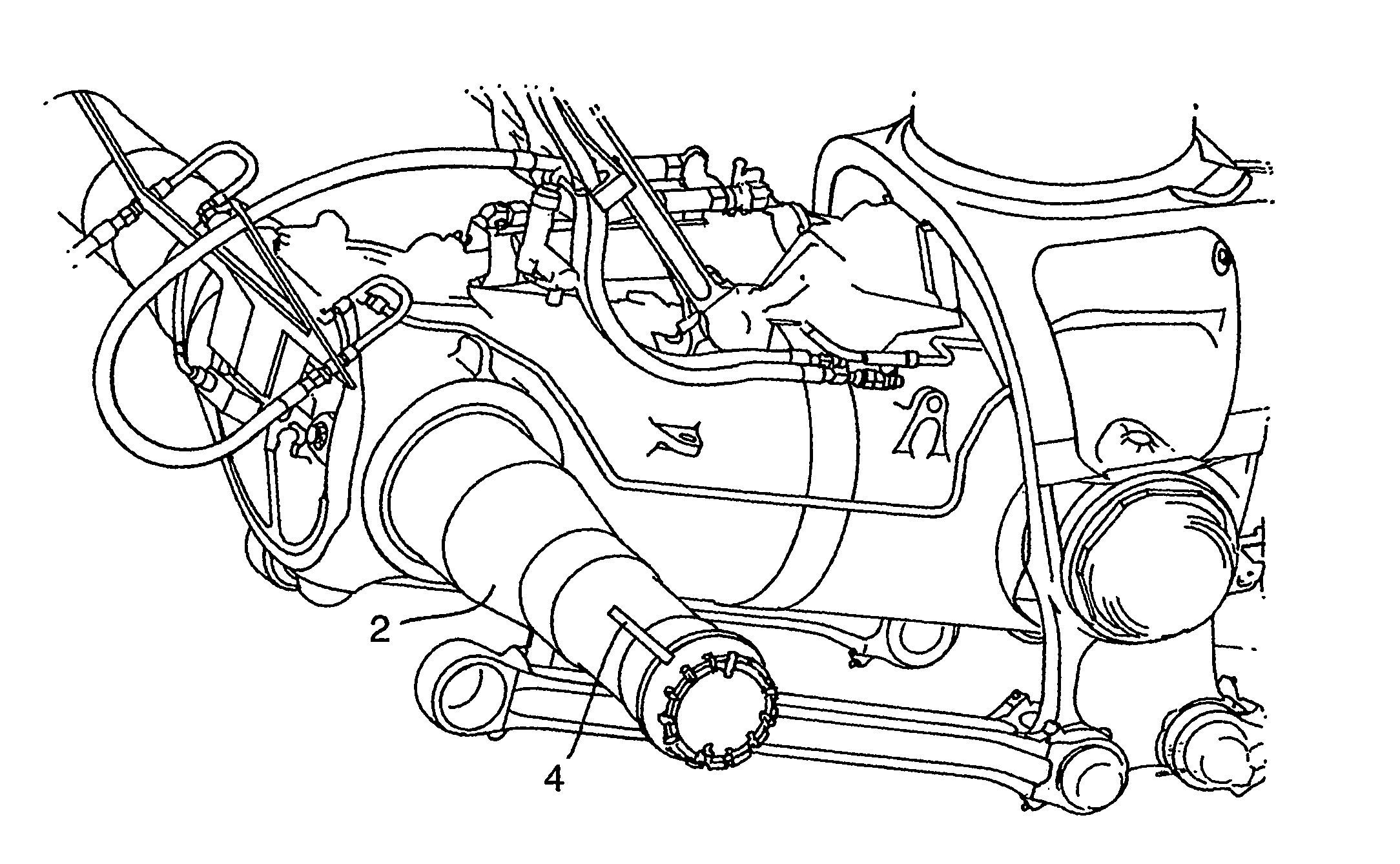
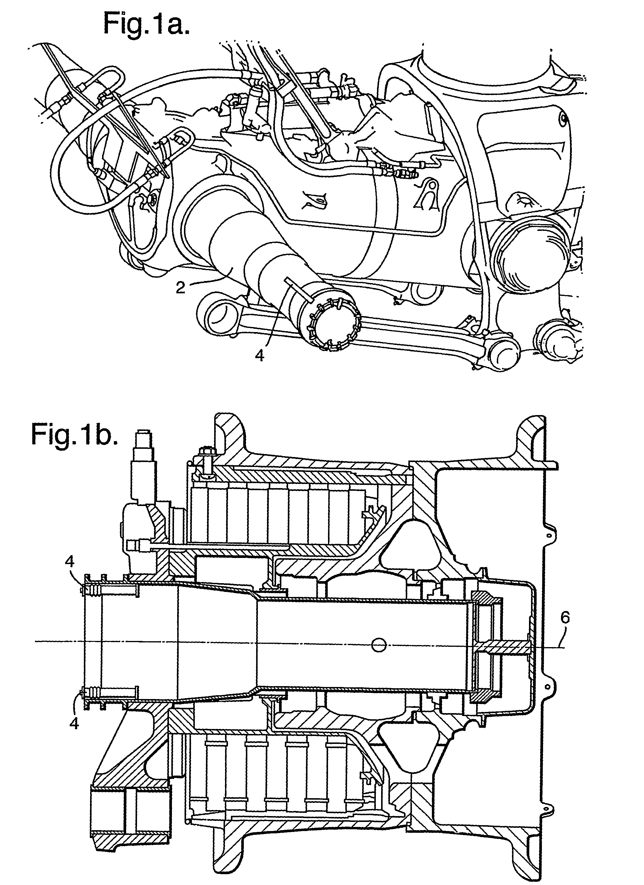
[0085]FIGS. 1a and 1b show a wheel axle 2 (the wheel itself not being shown in those Figures) including two load detectors 4 that form part of a load measuring system according to the invention. Each load detector 4 is in the form of a separate displacement measurement system 4. The load detectors 4 are provided to monitor the part of the braking force directly reacted through the wheel axle 2 and also to monitor the vertical load.

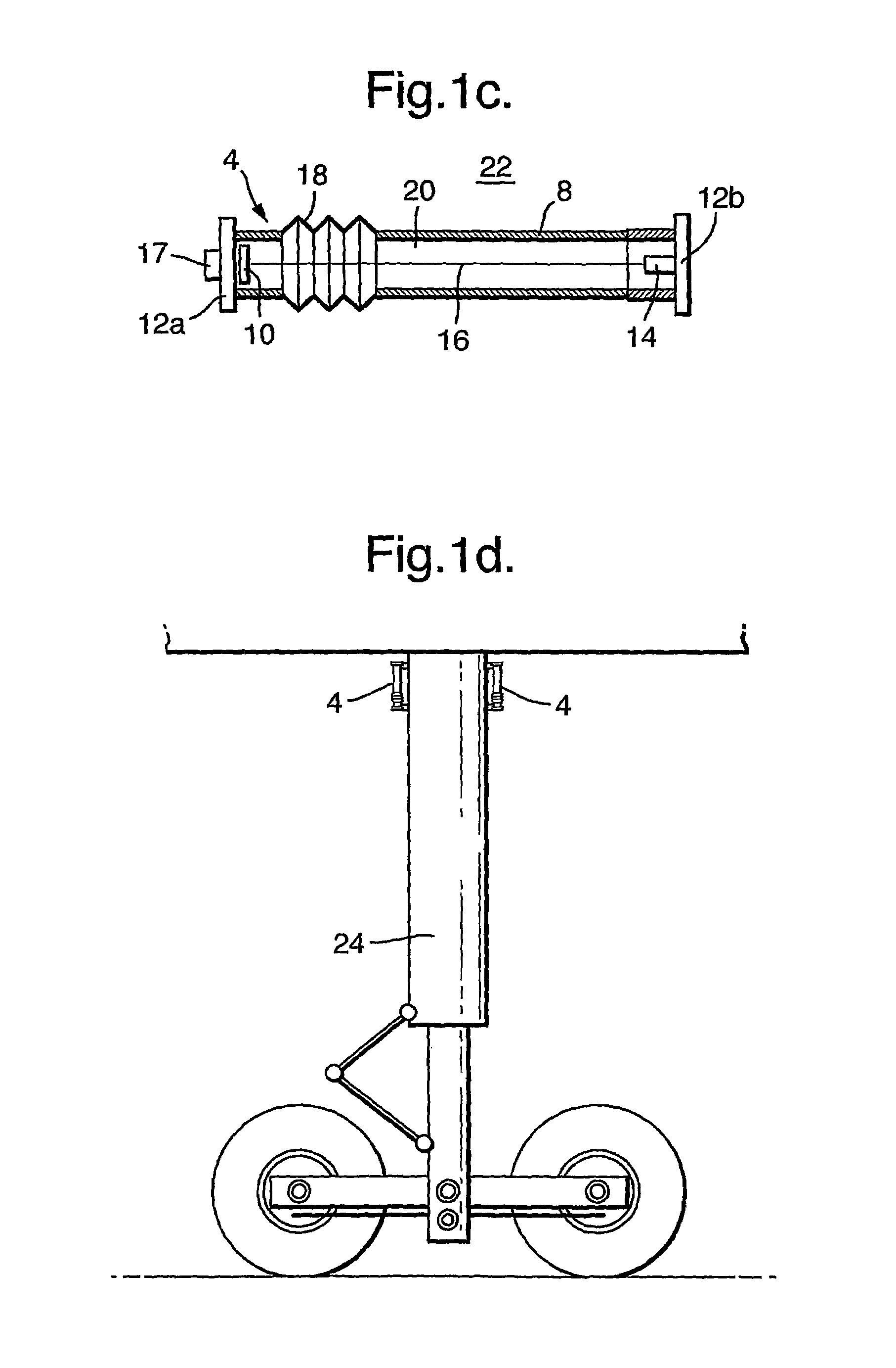
[0086]The two displacement measurement systems 4 (one of which being shown highly schematically in FIG. 1a) are elongate in shape and extend a short distance in the direction of the axis of the axle 2, their axes being spaced apart, and parallel to, and on opposite sides of, the central axis 6 of the wheel axle 2. With reference to FIG. 1c, each displacement measurement system 4 comprises a sealed cylindrical container 8 having one end 12a within which there is mounted a quad-cell photodiode detector 10 (a detector comprising four photodiodes) and an oppos...

second embodiment

[0101]FIGS. 2a and 2b show the invention. In this embodiment, the load measuring system receives load information concerning the loads on a brake pin 30. These measurements can either supplement or replace the measurements made in respect of loads on the wheel axle 2. As illustrated in FIG. 2b, the bogey 32 of the landing gear accommodates six wheels (not shown in FIG. 2b), each of which being mounted for rotation about an axle 2 on which there is also mounted a set of brakes comprising brake disks 34 and a piston housing 36. Torque during braking is reacted through a brake rod 38 that is attached to the brake piston housing 36 via a brake pin 30 (illustrated schematically in FIG. 2b). Thus, information concerning the braking torque and the vertical load reacted through the wheel may be measured by monitoring loads, and in particular shear loads, in the brake pin 30. FIG. 2a shows in cross-section the brake pin 30 and parts of the piston housing 36 and the brake rod 38.

[0102]The eff...


PUM


Abstract

The load on an aircraft component, such as the load on a landing gear leg during braking, is measured with a contactless, all-weather displacement measuring system. The system includes a control unit a controllable microwave emitter of electromagnetic radiation and a microwave detector comprising a plurality of antennae. When the aircraft component is subjected to a load relative movement of the emitter and detector is caused. The detector generates in response to microwave radiation received from the focused beam of radiation emitted by the emitter a signal that is received by a signal processor of the control unit. The signal received by the control unit depends on the relative positions of the emitter and detector. The control unit is arranged to provide an output signal representative of the load sustained by the aircraft component. The system may be used to control braking in dependence on the output signal so as to maximize braking efficiency without overloading the landing gear leg.

Description

BACKGROUND OF THE INVENTION[0001]The present invention relates to an aircraft including an apparatus for measuring the load sustained by an aircraft component and to a method of measuring such a load. In particular, the present invention relates to an apparatus for determining the load sustained by an aircraft when braking and / or maneuvering the aircraft on the ground.[0002]When an aircraft maneuvers on the ground (including, for example, immediately after touch down), the aircraft is subjected to various loads including vertical wheel to ground loads and horizontal drag loads including, for example, loads caused by friction between the tires of the wheels of the aircraft and the ground. The landing gear is subjected to significant horizontal loads on braking. The landing gear and other components of the aircraft have to be carefully designed in order for the aircraft to be able to withstand such loads, and other operational loads, but without unduly increasing the mass of the aircr...

Claims


Application Information

Patent Timeline
IPC IPC(8): G01L1/24B60T8/00B60T8/52B64C25/00B64C25/46B64C25/58G01L1/25
CPCB60T8/00B60T8/52B64C25/001G01L1/25B64C25/58B64C25/46B64D2045/008
Inventor GIAZOTTO, ALESSANDRO RICCARDO BRITANNICO
Owner AIRBUS UK
Why Eureka
Try Eureka