Power transmission device for hybrid vehicle

a technology for power transmission devices and hybrid vehicles, which is applied in the direction of electric propulsion mounting, transportation and packaging, gearing, etc., can solve the problems of disadvantageous layout and mounting of respective components, overall length of engine room, and difficulty in common application of such a power transmission device to a plurality of different platforms

Active Publication Date: 2009-08-25
HYUNDAI MOTOR CO LTD
View PDF13 Cites 24 Cited by
  • Summary
  • Abstract
  • Description
  • Claims
  • Application Information

AI Technical Summary

Benefits of technology

[0014]Accordingly, the present invention has been made in an effort to solve the above-described drawbacks and an object of the present invention is to provide a power transmission device for a hybrid vehicle, in which a torsion damper is disposed between an automatic transmission and a motor so that a flywheel, a motor rotor, an engine clutch and a retainer have the same inertia, thus providing a high damping force against engine fluctuation at low RPM operation by an engine and having an effective layout in terms of driving performance at low RPM by the engine and in terms of NVH (noise, vibration and harshness).

Problems solved by technology

Since the power transmission device for a hybrid vehicle has a structure in which the automatic transmission, the motor, the torque converter, the engine and the ISG are arranged in a row, the overall length of the engine room is increased, and thus it is disadvantageous in terms of the layout and mounting of the respective components.
Moreover, it is difficult to commonly apply such a power transmission device to a plurality of different platforms.
For conventional power transmission devices for a hybrid vehicle, a primary inertia in front of a damper spring of the device has a limited structure, the driving performance at a low RPM is degraded.

Method used


Image

  • Power transmission device for hybrid vehicle
  • Power transmission device for hybrid vehicle
  • Power transmission device for hybrid vehicle

Examples


Embodiment Construction

[0025]Reference will now be made in detail to the preferred embodiment of the present invention, examples of which are illustrated in the drawings attached hereinafter, wherein like reference numerals refer to like elements throughout. The embodiments are described below so as to explain the present invention by referring to the figures.

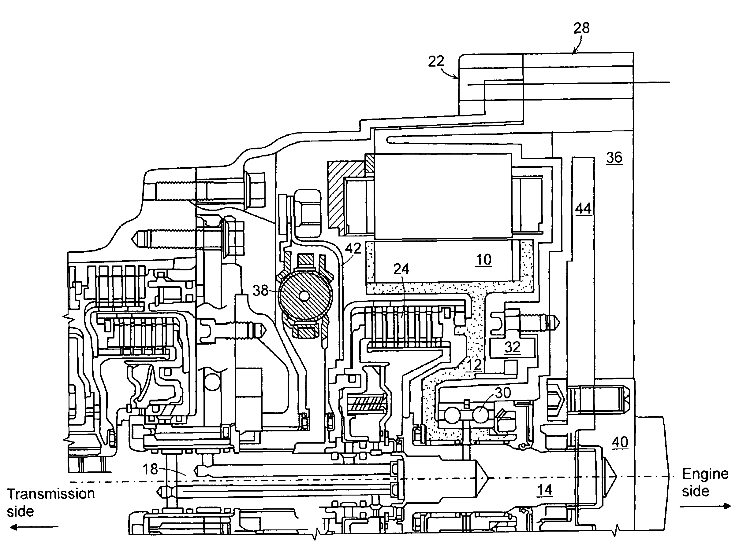
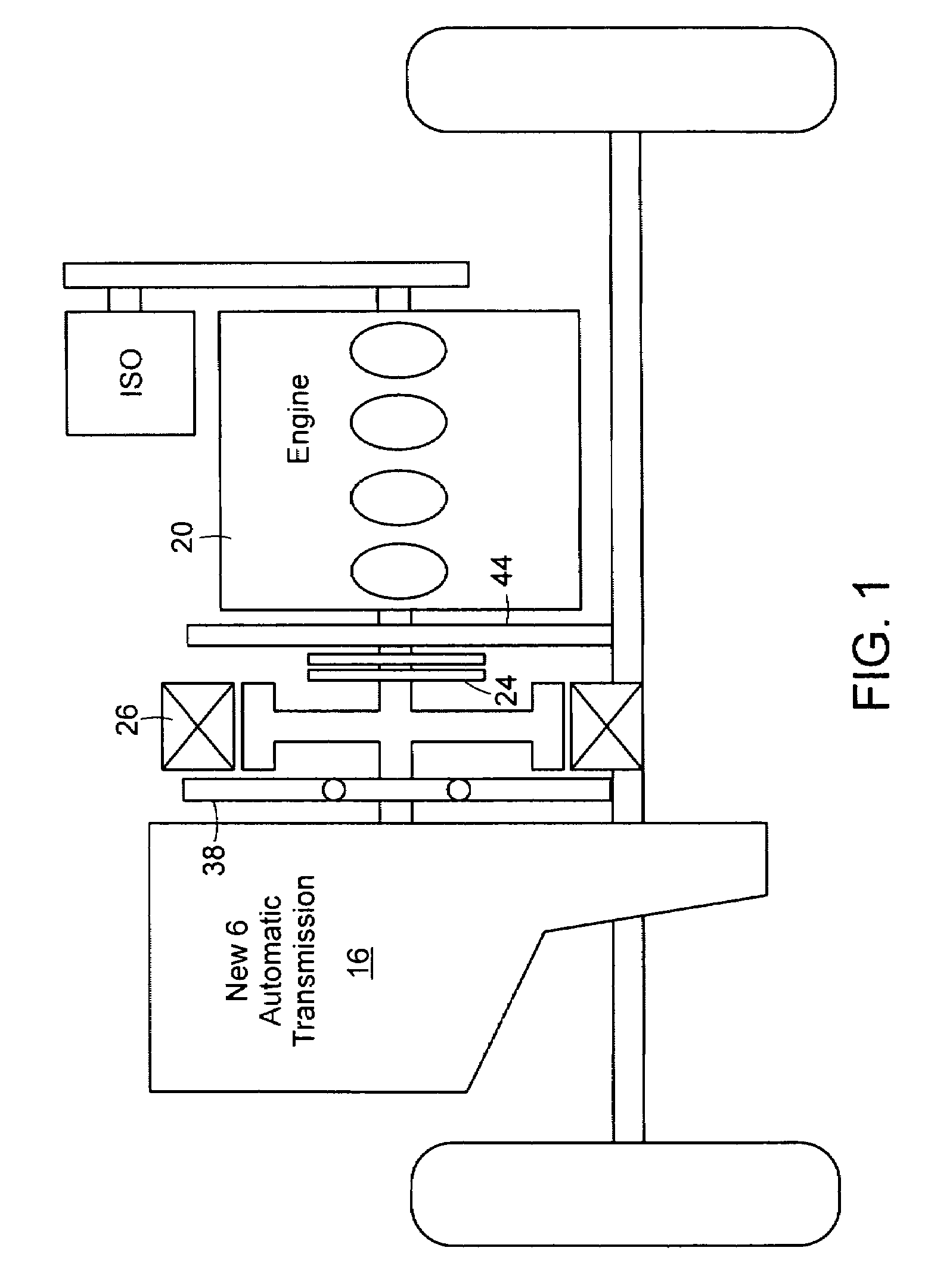
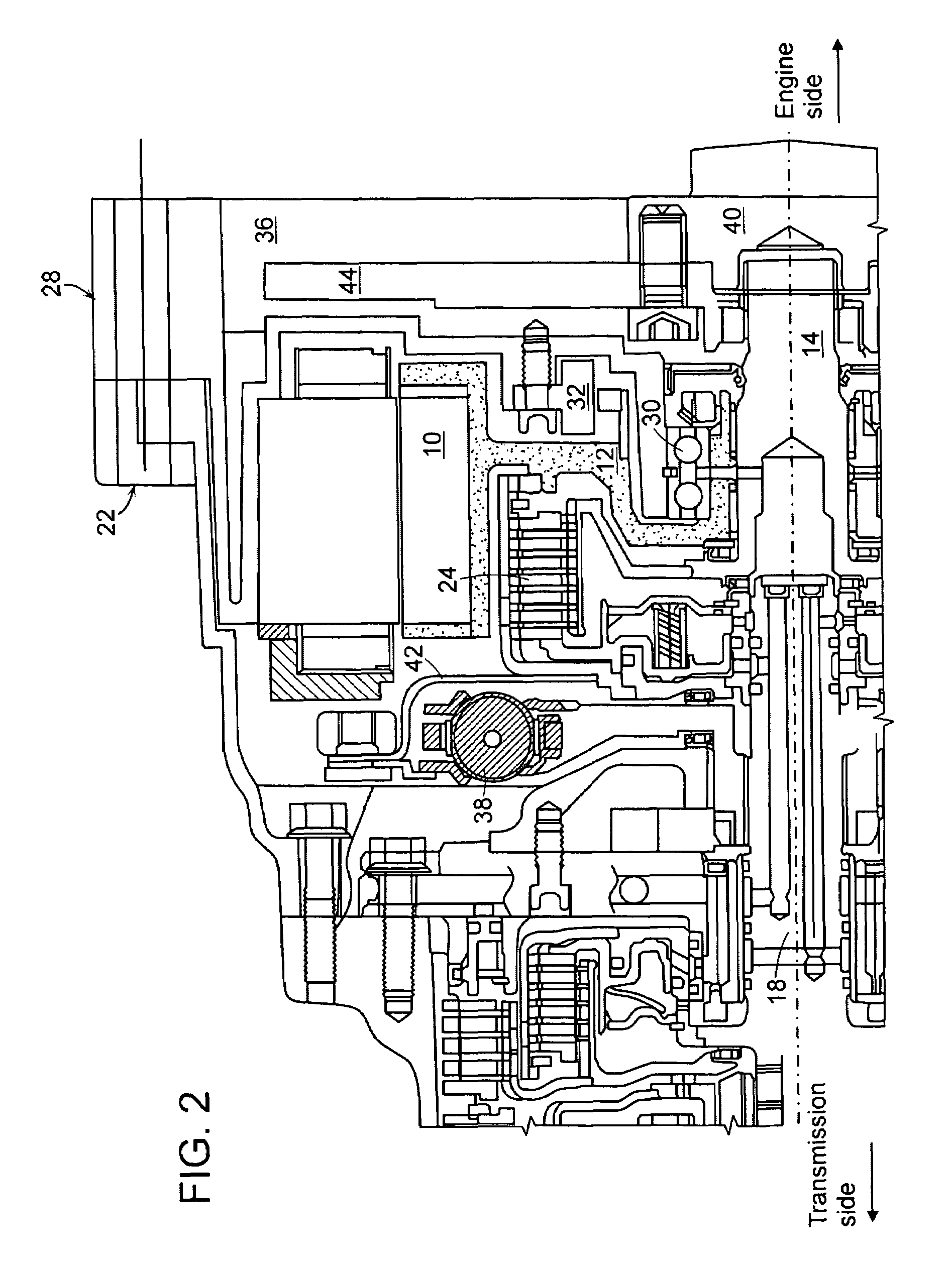
[0026]FIG. 1 is a schematic diagram illustrating the power transmission of a power transmission device for a hybrid vehicle in accordance with the present invention, and FIG. 2 is a schematic cross-sectional view illustrating the structure of a power transmission device for a hybrid vehicle in accordance with the present invention.

[0027]A power transmission device for a hybrid vehicle in accordance with the present invention has a layout in which an automatic transmission 16 having an input shaft 18, a motor 26 and an engine 20 are directly connected to the same axis, a torsion damper 38 is disposed between the automatic transmission 16 and the motor...


PUM


Abstract

The present invention provides a layout of a power transmission device for a hybrid vehicle which provides a high damping force a high damping force against engine fluctuation at low RPM operation by an engineFor this, the preset invention provides a power transmission device for a hybrid vehicle, in which an automatic transmission having an input shaft, a motor, an engine clutch, a flywheel, and an engine having an output shaft connected to a crank shaft of the engine are directly connected to the same axis, the power transmission device including: a motor support shaft, the outer end of which is supported by a motor rotor and the inner end of which extends toward the boundary between the output shaft of the engine and the input shaft of the automatic transmission; a motor housing arranged so as to surround the outer circumference and the left side surface of the motor rotor; a torsion damper disposed between the left side end of the motor housing and the motor rotor; an engine clutch, disposed between the left side end of the motor housing and the left side surface of the inner end of the motor support shaft, for power transmission between the output shaft of the engine and the input shaft of the automatic transmission; a retainer connecting a housing of the engine clutch to the torsion damper; a motor cover housing arranged to cover the right side surface of the motor rotor and the right side surface of the inner end of the motor support shaft and including a concave portion on the right side surface thereof; and a flywheel positioned at the concave portion of the motor cover housing to be blocked from the motor rotor.

Description

CROSS-REFERENCE TO RELATED APPLICATION[0001]This application claims under 35 U.S.C. §119(a) on Korean Patent Application No. 10-2007-0089881, filed on Sep. 5, 2007, the entire contents of which are incorporated herein by reference.BACKGROUND[0002](a) Technical Field[0003]The present invention relates to a power transmission device for a hybrid vehicle. More particularly, the present invention relates to a power transmission device for a hybrid vehicle, which provides a high damping force against engine fluctuation at low RPM operation by an engine and has an effective layout in terms of driving performance at low RPM by the engine and in terms of NVH (noise, vibration and harshness).[0004](b) Background Art[0005]In general, a power transmission device for a hybrid vehicle has a layout in which an automatic transmission, a motor, an engine and an integrated starter-generator (ISG) are arranged in a row.[0006]In the hybrid vehicle using the engine and the motor, the motor which is eff...

Claims


Application Information

Patent Timeline
Patent Type & Authority Patents(United States)
IPC IPC(8): B60K1/00
CPCB60K6/365B60K6/405B60K6/48B60K6/485B60K6/547B60W10/08Y02T10/642B60W2510/081B60W2520/10Y02T10/6221Y02T10/6226B60L2240/421Y02T10/62Y02T10/64B60K6/50B60K17/06
Inventor KIM, KYUNG HA
Owner HYUNDAI MOTOR CO LTD
Why Eureka
Try Eureka