
Drive shaft reduction gear

a technology of reducing gear and reducing gear, which is applied in the direction of gear components, control devices, vehicle components, etc., can solve the problems of non-rotational support of the shaft portion of the ring gear, and achieve the effects of preventing deformation load, preventing fretting, and improving durability

Inactive Publication Date: 2009-08-25
KOMATSU LTD
View PDF4 Cites 6 Cited by
  • Summary
  • Abstract
  • Description
  • Claims
  • Application Information

AI Technical Summary

Benefits of technology

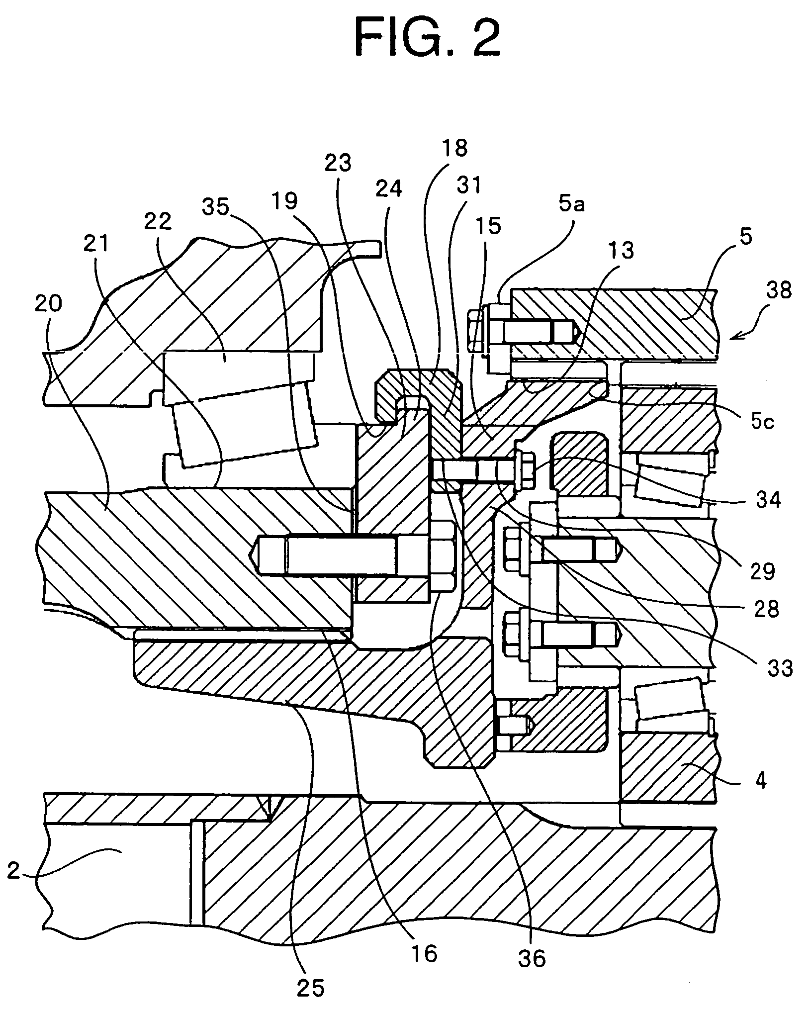
[0016]Accordingly, it is possible to prevent a deformation load from being applied between the shaft portion of the ring gear and the inner peripheral surface side of the drive shaft housing on the basis of the load applied from the driven body. In other words, it is possible to prevent the fretting from being generated between the shaft portion of the ring gear and the inner peripheral surface side of the drive shaft housing. Accordingly, it is possible to improve durability in the connection portion between the shaft portion of the ring gear and the inner peripheral surface side of the drive shaft housing.
[0017]Further, the shaft portion of the ring gear is supported by the inner peripheral surface of the shaft portion of the drive shaft housing. Accordingly, it is possible to assemble the ring gear hub in the drive shaft housing after assembling the bearing supporting the driven body in the drive shaft housing. Therefore, an assembling work can be easily executed, and it is possible to detach the ring gear hub from the drive shaft housing without detaching the bearing. Accordingly, it is possible to easily disassemble at the time of repairing, inspecting or the like.
[0018]Further, the structure is made such that the rotating force of the ring gear is not transmitted to the bearing holder holding the bearing in the axial direction. Accordingly, the bearing holder is not loosened by the rotating force of the ring gear. Further, since the ring gear hub is supported by the inner peripheral surface of the drive shaft housing, it is possible to reduce an outside dimension in a radial direction and a length in an axial direction of the drive shaft reduction gear. In accordance with these matters, it is possible to achieve a compact structure of the drive shaft reduction gear.
[0019]According to second and third aspects of the invention, a split ring can be employed as the locking means. Thus, a split piece of the split ring can be sequentially engaged with the bearing holder after the bearing holder is attached to the drive shaft housing. Accordingly, it is possible to easily assemble the split ring. Further, according to the third aspect, it is possible to easily execute an engaging work between the split ring and the bearing holder.

Problems solved by technology

Further, the shaft portion of the ring gear is non-rotatably supported by an inner peripheral surface side of the drive shaft housing without supporting the bearing.

Method used


Image

  • Drive shaft reduction gear
  • Drive shaft reduction gear
  • Drive shaft reduction gear

Examples


first embodiment

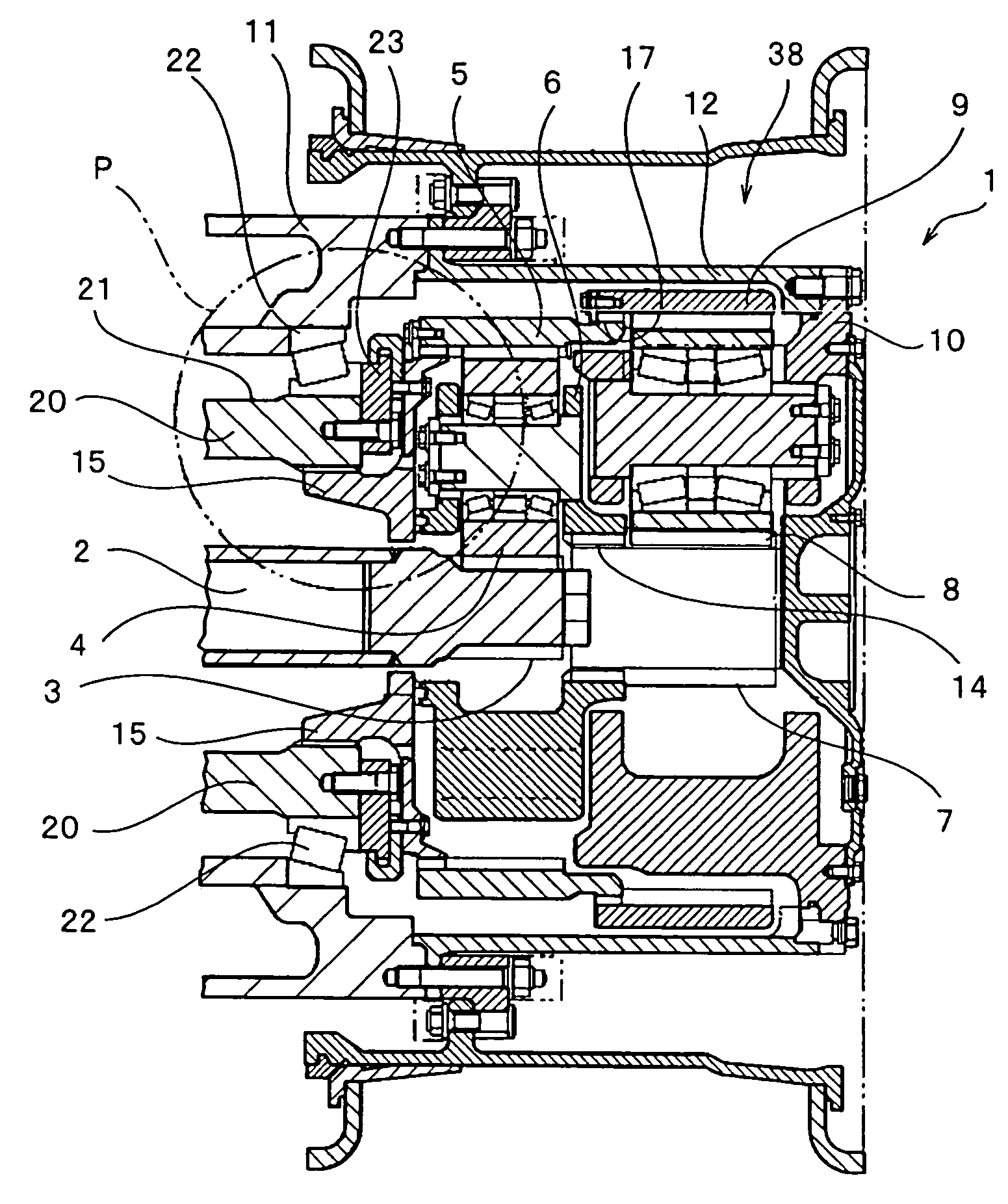
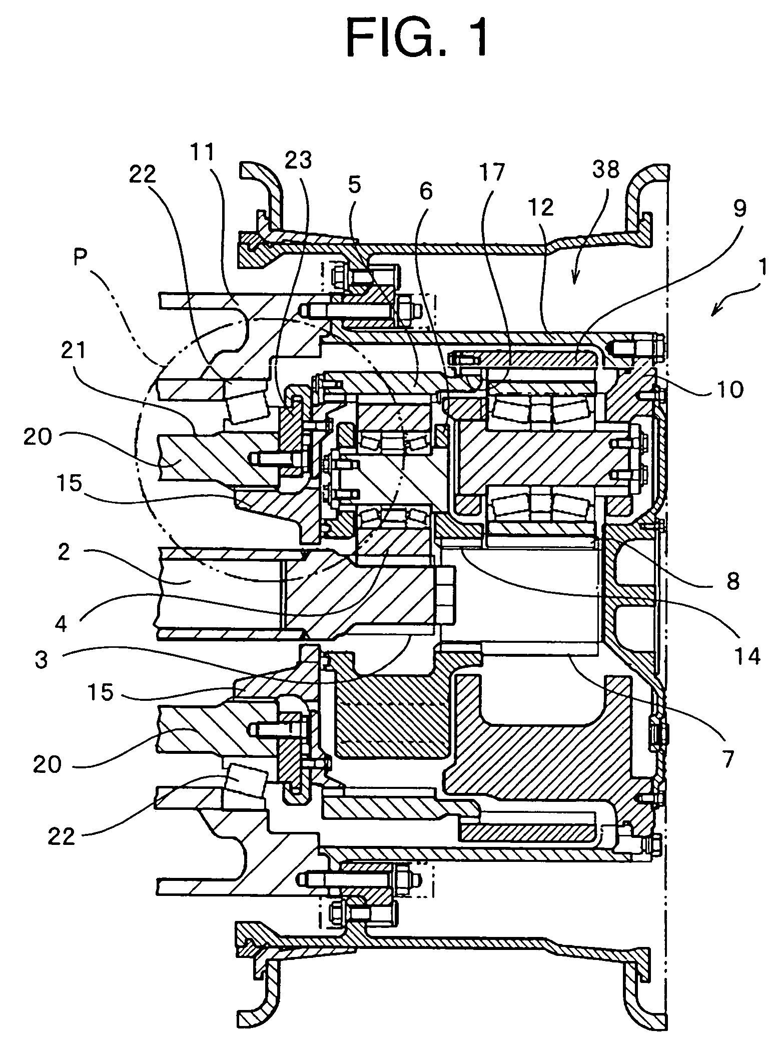
[0028]As shown in FIG. 1, a drive shaft reduction gear 1 is provided with a two-stage reduction planetary gear apparatus. The drive shaft reduction gear 1 can be structured such as to be provided with a single-stage reduction planetary gear apparatus or a multi-stage reduction planetary gear.

[0029]A drive shaft 2 branched by a differential gear or the like is arranged within an axle housing 20 corresponding to the drive shaft housing. A two-speed planetary gear apparatus 38 is arranged between the drive shaft 2 and a wheel hub 11.

[0030]The planetary gear apparatus 38 executes a first stage shift by a first sun gear 3 provided in a leading end of the drive shaft 2, a first ring gear 5 non-rotatably supported by a spline connection portion 16 with respect to the axle housing 20, and a first planetary gear 4 arranged between the first sun gear 3 and the first ring gear 5. A rotation of a first carrier 6 bearing the first planetary gear 4 is transmitted to a second sun gear 7 arranged i...

second embodiment

[0052]FIG. 4 shows a structure of another embodiment of the drive shaft reduction gear according to the invention. In a second embodiment, the structure of the locking means is differentiated from the structure of the locking means according to the first embodiment. The other structures have the same structures as those of the first embodiment. A description of the same structures as those of the first embodiment will not be repeated, using the same reference numerals used in the first embodiment.

[0053]A step portion 27 is formed between a spline connection portion 16 with an axle housing 20 and a flange portion 28 of a ring gear hub 15A, in an outer peripheral portion of a shaft portion 25 of the ring gear hub 15A. An inner end surface of a bearing holder 23A can be brought into contact with the step portion 27 mentioned above. A locking means for regulating the movement in the axial direction of the ring gear hub 15A is structured by an inner end surface of the bearing holder 23A ...

third embodiment

[0056]FIG. 5 shows a structure of another embodiment of the drive shaft reduction gear according to the invention. In a third embodiment, a split type stopper member 32 for regulating a movement in an axial direction of a ring gear hub 15B is provided as a structure of the locking means. In this regard, the structure is different from the locking means in the second embodiment.

[0057]The other structures have the same structures as those of the second embodiment. A description of the same structures as those of the first and second embodiments will not be repeated, using the same reference numerals used in the first and second embodiments.

[0058]A step portion 27 is formed between an axle housing 20A and a flange portion 28 of the ring gear hub 15B, in the outer peripheral surface of a shaft portion 25 of the ring gear hub 15B. The step portion 27 is brought into contact with the split type stopper member 32 pinched between a bearing holder 23B and the end portion of the axle housing ...


PUM


Abstract

A drive shaft reduction gear using a planetary gear mechanism and having a high durability, wherein a rotation of a drive shaft is transmitted to a wheel hub via the planetary gear mechanism, a ring gear hub provided in a first ring gear in the planetary gear mechanism is hooked to a bearing holder attached to an axle housing via a split ring, thereby a movement in an axial direction of the first ring gear is regulated, and further, a shaft portion provided in the ring gear hub is non-rotatably supported by an inner peripheral surface of a shaft end portion of the axle housing.

Description

BACKGROUND OF THE INVENTION[0001]1. Technical Field of the Invention[0002]This invention relates to a drive shaft reduction gear, which transmits a rotation of a drive shaft to a driven body via a planetary gear mechanism.[0003]2. Description of the Related Art[0004]As a drive shaft reduction gear provided with a planetary gear mechanism which has been conventionally used, there has been proposed a structure of an independent suspension axle described in Japanese Patent Application Laid-Open No. 8-40095 or the like. The structure of the independent suspension axle described in the publication of the patent application mentioned above has a cross sectional structure shown in FIG. 6.[0005]As shown in FIG. 6, in an axle housing 41 independently suspended by a vehicle body frame (not shown), a drive shaft 43, in which one end of the drive shaft is coupled to a universal joint 42, is supported at two points by a roller bearing 44 and a cylinder bush 45.[0006]A sun gear shaft 47 having a ...

Claims


Application Information

Patent Timeline
Patent Type & Authority Patents(United States)
IPC IPC(8): F16H57/08F16H57/02
CPCF16H57/082F16H57/021
Inventor MORITA, MITSUAKI
Owner KOMATSU LTD
Learn More