Illumination and imaging devices and methods

Active Publication Date: 2009-08-25
TELEDYNE FLIR LLC
View PDF9 Cites 72 Cited by
  • Summary
  • Abstract
  • Description
  • Claims
  • Application Information

AI Technical Summary

Benefits of technology

[0011]It is an aim of some embodiments of the invention to facilitate a user registering infr

Problems solved by technology

This limits areas where it is practical to use thermal imaging cameras.
Another problem with existing thermal imaging cameras is that it can be difficult for a user to register the thermal image presented to them on a imager display (often ghostly green) and the real visible word that they can see with their normal eyesight.
The head up display is typically about 10 cm×10 cm and although the windscreen of the automobile is about 200 cm×50 cm some drivers have a disturbing tendency when using the I.R. imaging system to look only through the small area of the head-up display: they may not scan the full view that they can see out of the windscreen properly at night and are psychologically reduced to driving using the head-up display alone (although the

Method used


Image

  • Illumination and imaging devices and methods
  • Illumination and imaging devices and methods
  • Illumination and imaging devices and methods

Examples


Embodiment Construction

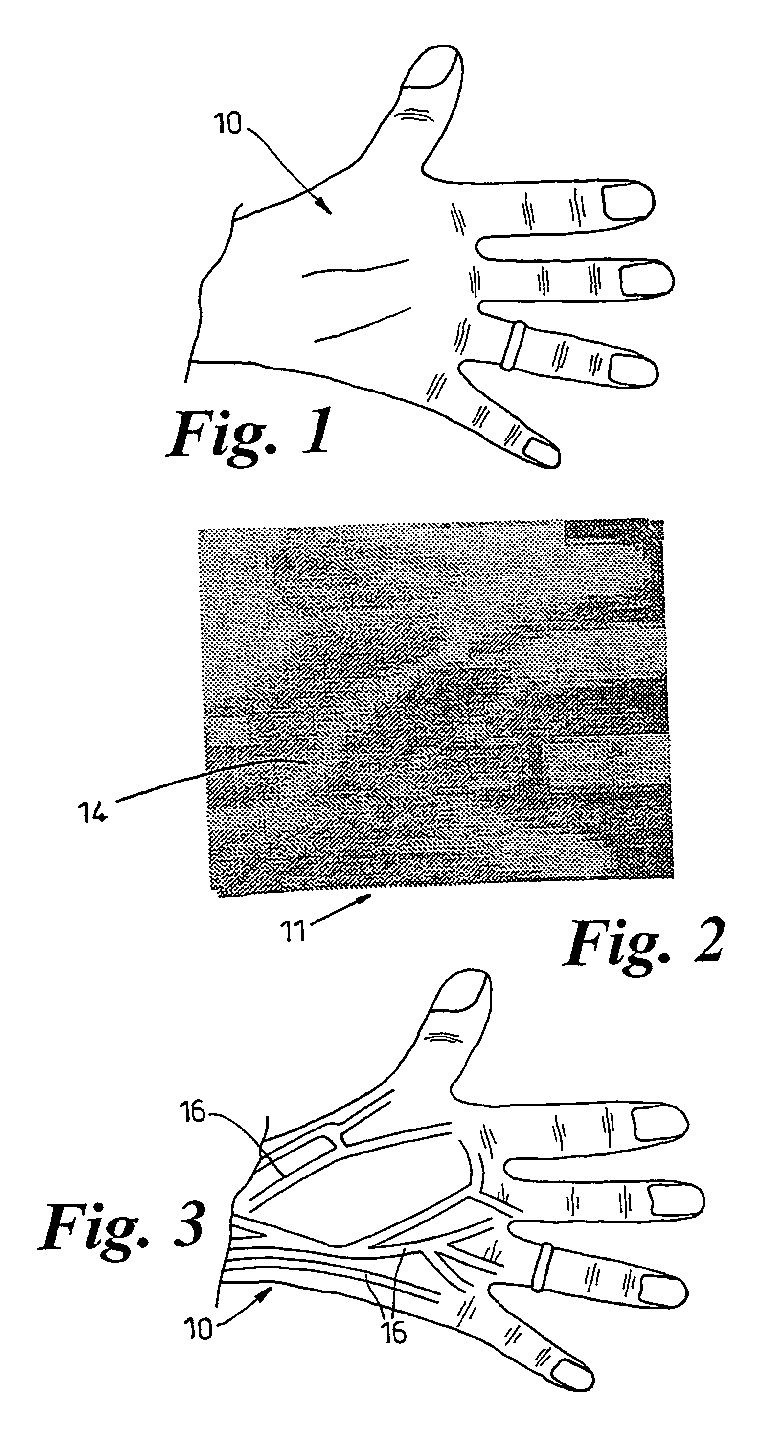
[0083]FIG. 1 shows a person's hand. It is difficult to see their veins. This can make it difficult to introduce a needle into a vein in the back of their hand.

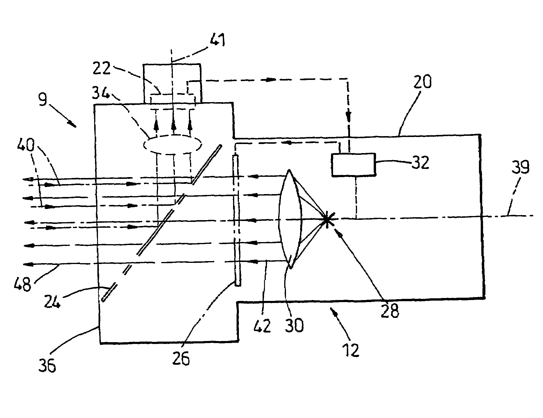
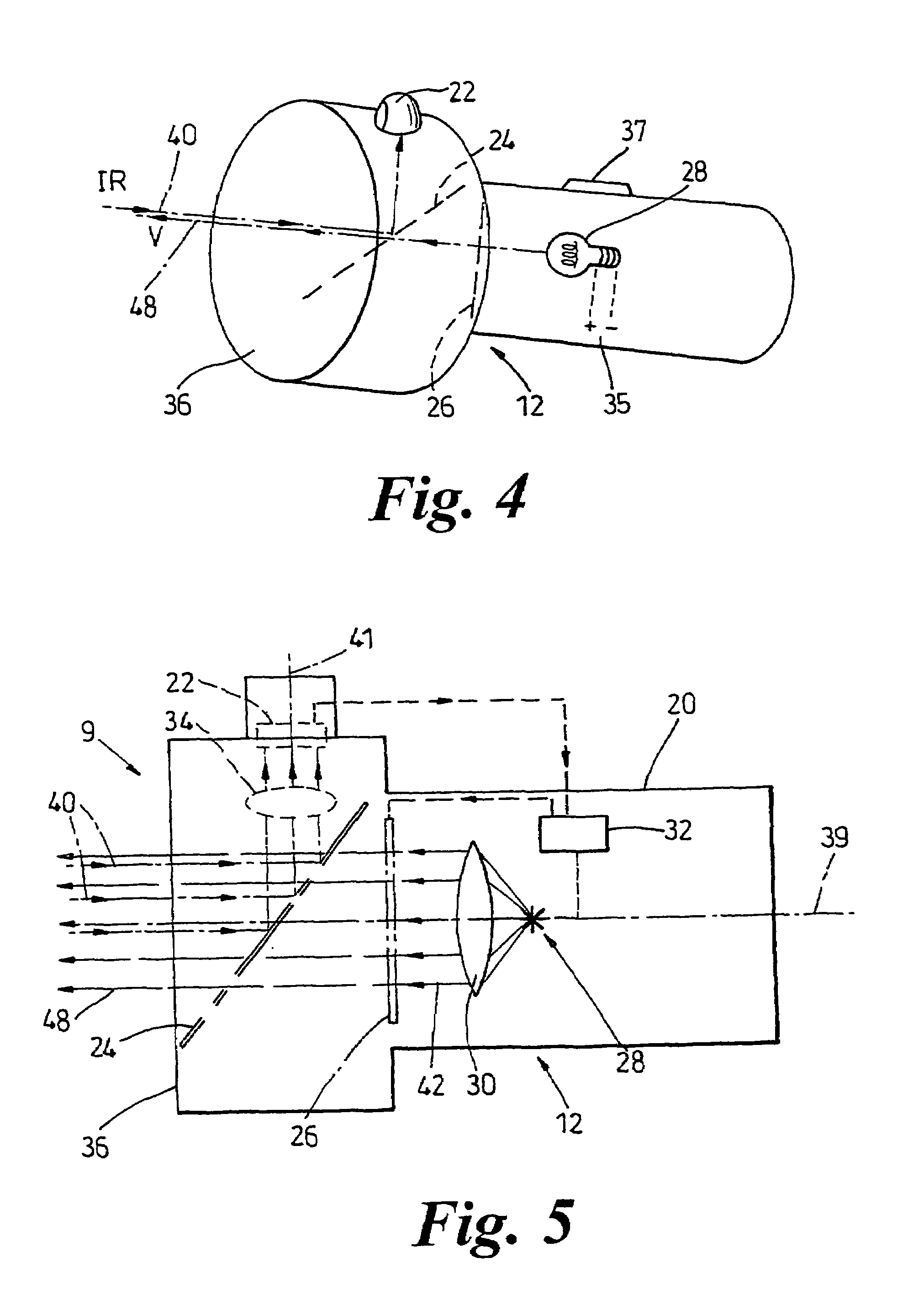
[0084]FIG. 2 shows an infrared image 11 obtained by a thermal torch 12 of the hand 10. The veins, because they are warmer than the remainder of the back of the hand, show up as white / pale lines 14. It will be appreciated from what follows that the image 11 is not shown to the user of the torch 12 on a screen and may only exist within its torch as data / signals.

[0085]FIG. 3 shows the person hand 10 as seen by the user of a thermal torch 12 (shown in FIGS. 4 and 5). Lines 16 of white light are projected onto the hand 10 overlying the veins as detailed in the thermal image 11. The user can therefore take the torch 12, shine it on a patient's hand and see using their normal eyesight where the veins are because the torch picks them out in visible light. The torch could, of course, pick the veins out in blue, or red, or another non-w...


PUM


Abstract

A thermal torch (12) comprises an infrared camera (22) and a visible light emitter (28, 26) arranged so as to illuminate hot objects with visible light. This projection of visible light onto the scene, rather than observing it at infrared wavelengths converted to visible light by a display screen, makes viewing the scene more natural. Applications include medical imaging equipment, night driving systems, stage lights, and security lights. The profile of the beam of visible light can be modulated with a beam profiler (26) which may be a LCD. The infrared camera (22) and visible projector (28,26) may be bore-sighted to facilitate overlying of the visible projected image onto the scene.

Description

[0001]This application is the U.S. national phase of international application PCT / GB01 / 00772 filed 23 Feb. 2001, which designated the U.S.BACKGROUND OF THE INVENTION[0002]1. Field of the Invention[0003]This invention relates to illuminating an observed scene with electromagnetic radiation, and to imaging. It is especially, but not exclusively, concerned with projecting light in a predetermined controlled beam, and has especial, but not exclusive, applications in thermal imaging.[0004]The invention arose in the field of thermal imaging and will be described in relation to that, but as will be appreciated it has wider applications.[0005]2. Discussion of Prior Art[0006]Infra thermal imagers exist and work well. To obtain good resolution pictures, for example 512×512 pixels, it is necessary to use expensive infrared cameras which now cost around £10,000 each. This limits areas where it is practical to use thermal imaging cameras.[0007]It is an aim of at least one aspect of the inventio...

Claims


Application Information

Patent Timeline
IPC IPC(8): G02B23/12H04N7/18
CPCG02B23/12F21W2131/406G03B17/54G03B21/142H04N5/33H04N9/3141H04N23/60A61B5/489A61B2090/366A61B5/01G01J5/0022G01J2005/0077H04N9/3161
Inventor KAUSHAL, TEJ
Owner TELEDYNE FLIR LLC
Why Eureka
Try Eureka