Power system protection system

a protection system and power system technology, applied in the direction of program control, multi-programming arrangement, instruments, etc., can solve the problems of system voltage dropping, system voltage dropping, system voltage dropping,

Inactive Publication Date: 2009-08-25
THE TOKYO ELECTRIC POWER CO INC +1
View PDF6 Cites 9 Cited by
  • Summary
  • Abstract
  • Description
  • Claims
  • Application Information

AI Technical Summary

Benefits of technology

[0011]Moreover, the load shedding output unit may be configured so as to determine the influence of the voltage drop resulting from the reactive power characteristic based on both or at least one of the load voltage and the load power factor of the loads connected to a lower substation and sequentially shed loads starting from those of the lower substation suffering more from the influence of the voltage drop resulting from the reactive power characteristic, or further, the load shedding output unit may be configured so as to output a load shedding command earlier for the lower substation having a lower load voltage and a smaller load power factor by shortening its time limit operation.
[0016]In addition, the load shedding output unit may be configured so as to determine the influence of the voltage drop resulting from the reactive power characteristic based on both or at least one of the load voltage and the load power factor of the loads connected to a lower substation and sequentially shed loads starting from those of the lower substations suffering more from the influence of the voltage drop resulting from the reactive power characteristic, or further, the load shedding output unit may be configured so as to output a load shedding command early for the lower substations having a lower load voltage and a smaller load power factor by shortening its time limit operation.
[0020]The system voltage gradual drop determination unit may be configured so as to have predetermined values that become smaller from a short determination time region of a voltage gradual drop toward a long determination time region in a long time region, and quickly detect a large voltage drop rate in the short determination time region and detect a small voltage drop rate in the long determination time region.
[0021]In addition, the load shedding output unit may be configured so as to determine the influence of the voltage drop resulting from the reactive power characteristic based on both or at least one of the load voltage and the load power factor of the loads connected to a lower substation and sequentially shed loads starting from those of the lower substations suffering more from the influence of the voltage drop resulting from the reactive power characteristic, or further, the load shedding output unit may be configured so as to output a load shedding command earlier for the lower substations having a lower load voltage and a smaller load power factor by shortening its time limit operation.
[0024]The system voltage gradual drop determination unit may be configured so as to have predetermined values that become smaller from a short determination time region of a voltage gradual drop toward a long determination time region in a long time region, and quickly detect a large voltage drop rate in the short determination time region and detect a small voltage drop rate in the long determination time region.
[0025]Moreover, the load shedding output unit may be configured so as to determine the influence of the voltage drop resulting from the reactive power characteristic based on both or at least one of the load voltage and the load power factor of the loads connected to a lower substation and sequentially shed loads starting from those of the lower substations suffering more from the influence of the voltage drop resulting from the reactive power characteristic, or further, the load shedding output unit may be configured so as to output a load shedding command earlier for the lower substations having a lower load voltage and a smaller load power factor by shortening its time limit operation.

Problems solved by technology

In a power system, when a power flow increases suddenly or a considerable imbalance between demand and supply of reactive power occurs, there may be the case where the system voltage drops considerably.
On the other hand, an increase in system load also causes the system voltage to drop and there may be the case where, for example, an increase in air-conditioning load at the power peak in summer causes the system voltage to drop considerably.
Therefore, if the terminal voltage drops due to an increase in air-conditioning load, the reactive power consumed increases suddenly and the system voltage of the power system drops all the more due to a sudden increase in reactive power, and it becomes difficult to stably maintain the system voltage.
In this case, depending on how a predetermined value of the system voltage is selected, there may be the case where unnecessary load shedding is performed at the time of regular voltage variations in the system voltage or of large electric power oscillation.
However, in a power system in which a plurality of bus-bars is connected by transmission network, high system loads are connected to the entire power system and power is supplied from each of the bus-bars, therefore, it is practically impossible to find the admittance of the system loads of the entire power system.
Therefore, even if connected by the transmission network, there are variations in various electrical characteristics among the respective bus-bars and it is difficult to handle various kinds of electric quantity as a single power system.

Method used


Image

  • Power system protection system
  • Power system protection system
  • Power system protection system

Examples


first embodiment

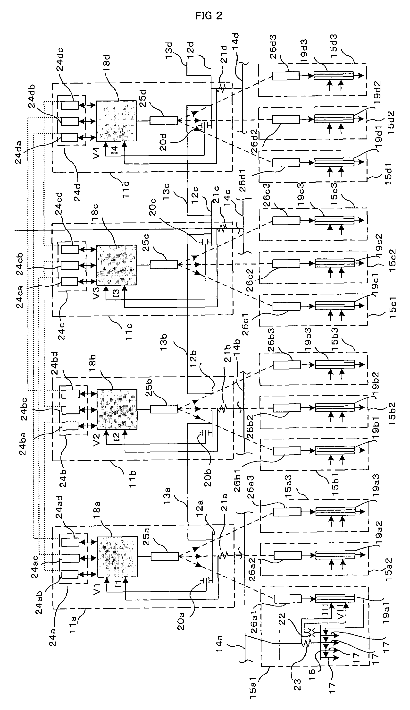
[0157]As described above, detection of voltage drop of the system voltage resulting from the reactive power characteristic is performed based on the voltage drop and the voltage drop rate of the system voltage in a plurality of upper substations connected by transmission network, therefore, it is possible to perform detection suitably even if a plurality of power transmission lines are configured in a network.

[0158]Further, both the voltage drop in the long time region of the order of several seconds to several minutes and the voltage drop in the short time region of the order of several seconds are detected separately, therefore, a wide detection is enabled. Furthermore, loads are shed selectively from the portions where a drop in the load voltage is large in accordance with the respective voltage drop characteristics of the voltage drop in the long time region and the voltage drop in the short time region, or a malfunction resulting from the voltage drop due to a system failure e...

second embodiment

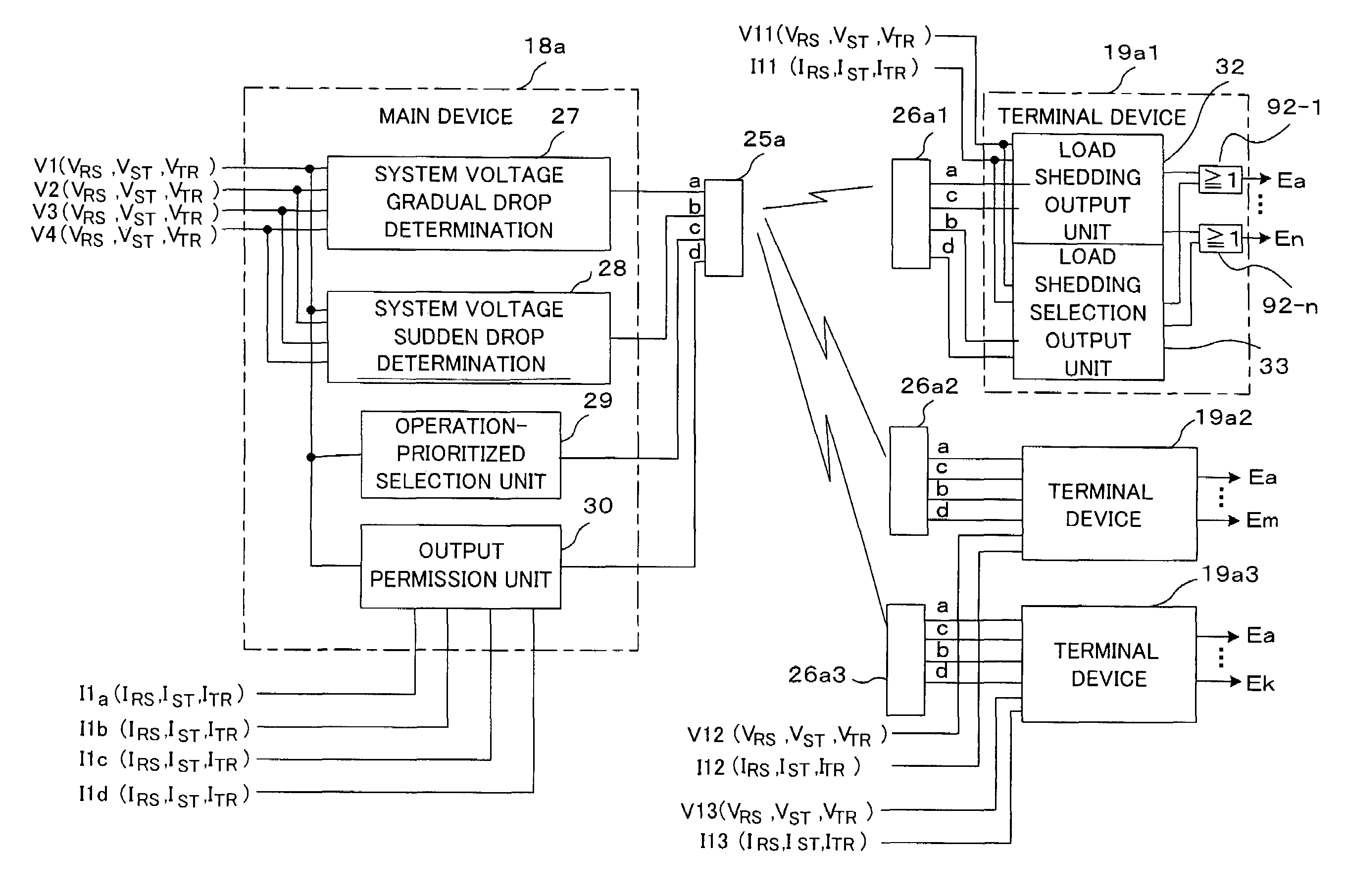
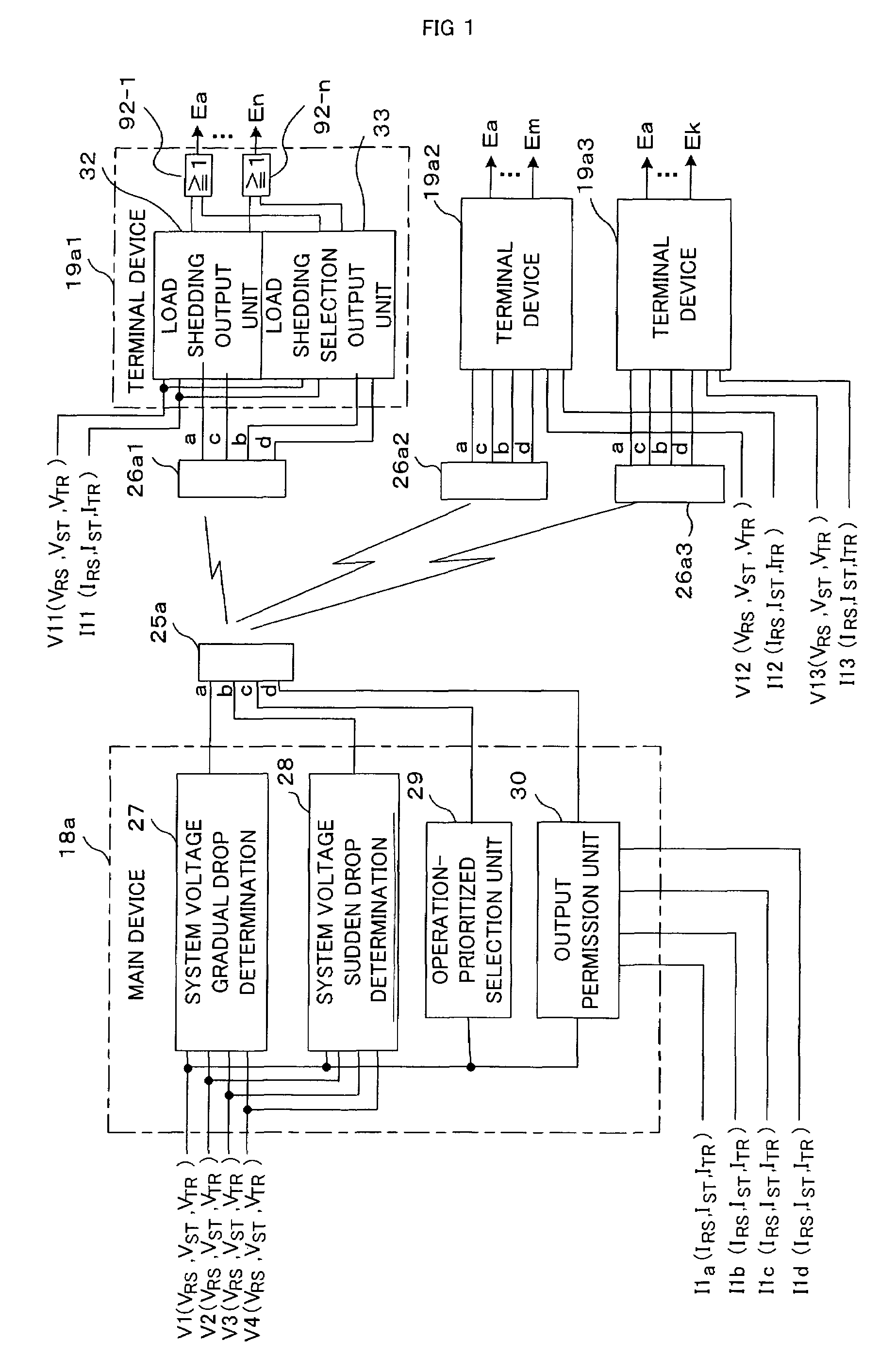
[0160]The operation-prioritized selection unit 29 outputs the operation-prioritized selection signal c so that the system voltage gradual drop determination signal a of the system voltage gradual drop determination unit 27 of its own is selected with priority in the terminal devices 19a1 to 19a3 when the voltage drop in the system voltage of the upper substation of its own is comparatively large. However, the bus-bars of the plurality of upper substations are connected by transmission network, therefore, the system voltage of the upper substation of its own is recovered eventually even if the load connected to other upper substation is shed first. Therefore, no problem will be brought about even if the operation-prioritized selection unit 29 is not provided in particular, therefore, the operation-prioritized selection unit 29 is not provided in the

[0161]Further, the output permission unit 30 determines whether or not the voltage sudden drop results from the reactive power characteri...

third embodiment

[0170] the power system protection system can be configured by suitably combining the system voltage gradual drop detection unit 27, the system voltage sudden drop detection unit 28, the operation-prioritized selection unit 29, and the output permission unit 30 in accordance with the system configuration of the power system in which power is supplied to loads directly from the substation of its own or the characteristic of the power system, therefore, it is possible to perform an optimum detection of a voltage drop in accordance with a power system.

INDUSTRIAL APPLICABILITY

[0171]As described above, the power system protection system according to the present invention can be applied to detection of a voltage drop resulting form the reactive power characteristic of the system voltage of an upper substation. Further, the voltage drop resulting from the reactive power characteristic is detected based on the voltage drop and the voltage drop rate of the system voltage of the upper substat...


PUM


Abstract

A power system protection system prevents a voltage drop resulting from the reactive power characteristic of a power system. A main device for acquiring a system electric quantity of one or a plurality of upper substations detects a voltage drop resulting from the reactive power characteristic of the power system and transmits a detection signal of the voltage drop to a terminal device for acquiring a system electric quantity of one or a plurality of lower substations. Each terminal device sequentially sheds loads starting from those suffering more from the influence of the voltage drop resulting from the reactive power characteristic based on the load voltage and load current of a load bus.

Description

TECHNICAL FIELD[0001]The present invention relates to a power system protection system for stably operating a power system.BACKGROUND ART[0002]In a power system, when a power flow increases suddenly or a considerable imbalance between demand and supply of reactive power occurs, there may be the case where the system voltage drops considerably. When the system voltage drops, an attempt is made to recover the system voltage to stably maintain the system voltage by the reactive power control by a generator linked to the power system or by the reactive power supply by a phase modifying equipment.[0003]On the other hand, an increase in system load also causes the system voltage to drop and there may be the case where, for example, an increase in air-conditioning load at the power peak in summer causes the system voltage to drop considerably. The air-conditioning load has the same characteristic as that of an induction motor load, in which when the terminal voltage drops below a certain v...

Claims


Application Information

Patent Timeline
Patent Type & Authority Patents(United States)
IPC IPC(8): H02J3/14H02J3/00H02J3/18
CPCH02J3/18Y02E40/30H02J3/38
Inventor YANAGIHASHI, KENSUZUKI, MAMORUMAEDA, TAKAFUMIISHIBASHI, AKIRANISHITANI, YASUCHIKA
Owner THE TOKYO ELECTRIC POWER CO INC
Why Eureka
Try Eureka