
Flat panel display having enhanced thermal dissipation uniformity

a technology of thermal dissipation uniformity and flat panel display, which is applied in the field of flat panel display, can solve the problems of poor image display and distortion of emission beam, and achieve the effect of improving thermal dissipation uniformity

Inactive Publication Date: 2009-08-25
SAMSUNG SDI CO LTD
View PDF10 Cites 4 Cited by
  • Summary
  • Abstract
  • Description
  • Claims
  • Application Information

AI Technical Summary

Benefits of technology

The present invention provides a flat panel display with improved heat dissipation uniformity. The display includes an image display panel with a transparent conductive film on the front side and a chassis member on the rear side. A conductive member connects the transparent conductive film and the chassis member. The transparent conductive film is coated with a conductive substance and formed of a thermal conductive substance to conduct heat to the chassis member. The conductive member is formed in a conductive tape of copper substance and is formed in edge areas of the front, side, and rear of the image display panel to connect the chassis member with the transparent conductive film.

Problems solved by technology

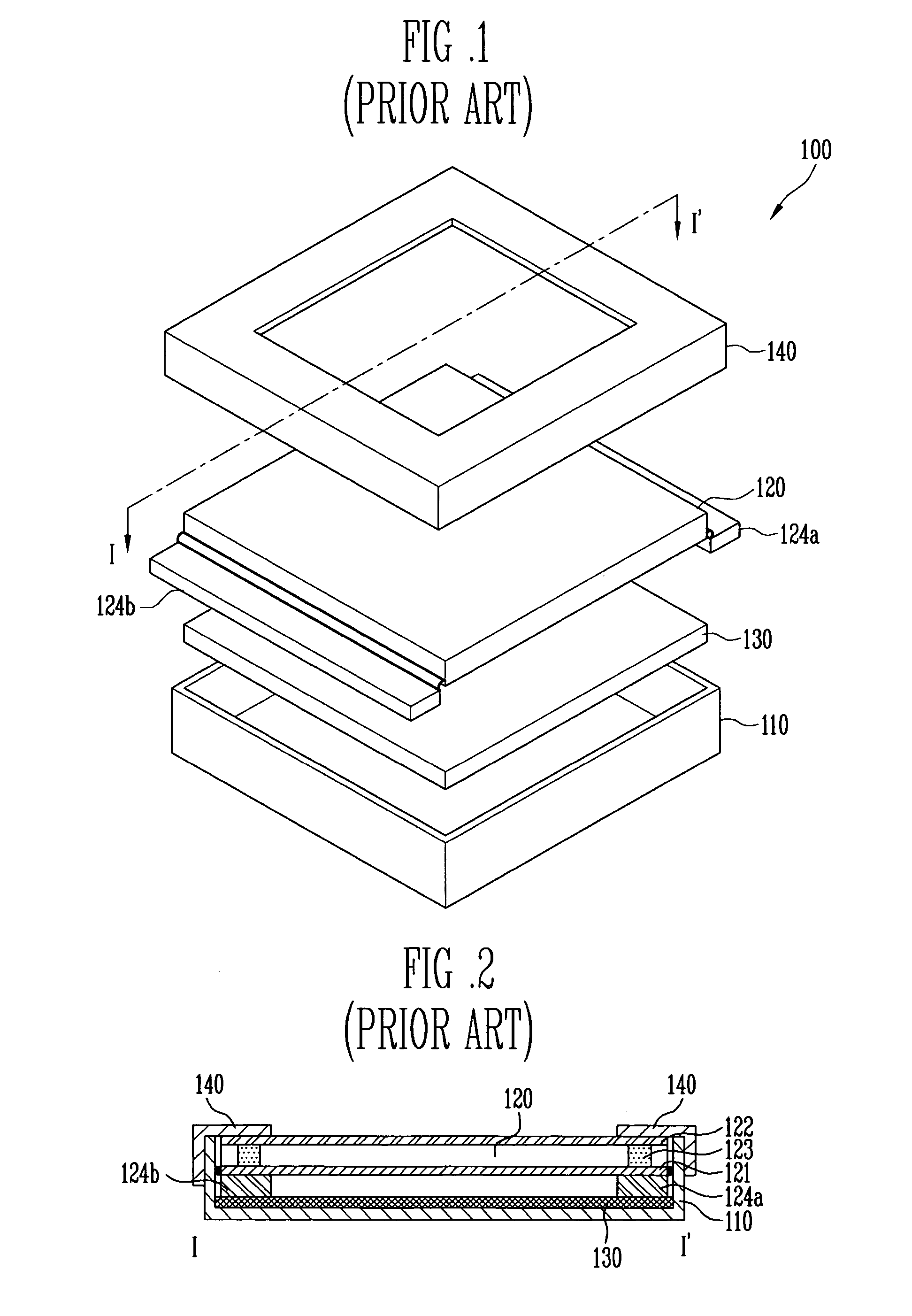
However, when the chassis member 130 contacts only the rear side of the second substrate of the image display panel to reduce the temperature of the second substrate and, due to the typical rigidity of a spacer between the first substrate and the second substrate, non-uniformity in the temperature between the first substrate and the second substrate can result, and, in turn, cause distortion of the emission beam.
The phosphor around the spacer then fails to light-emit uniformly, resulting in poor image display.

Method used


Image

  • Flat panel display having enhanced thermal dissipation uniformity
  • Flat panel display having enhanced thermal dissipation uniformity
  • Flat panel display having enhanced thermal dissipation uniformity

Examples


Embodiment Construction

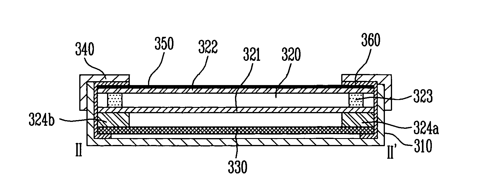
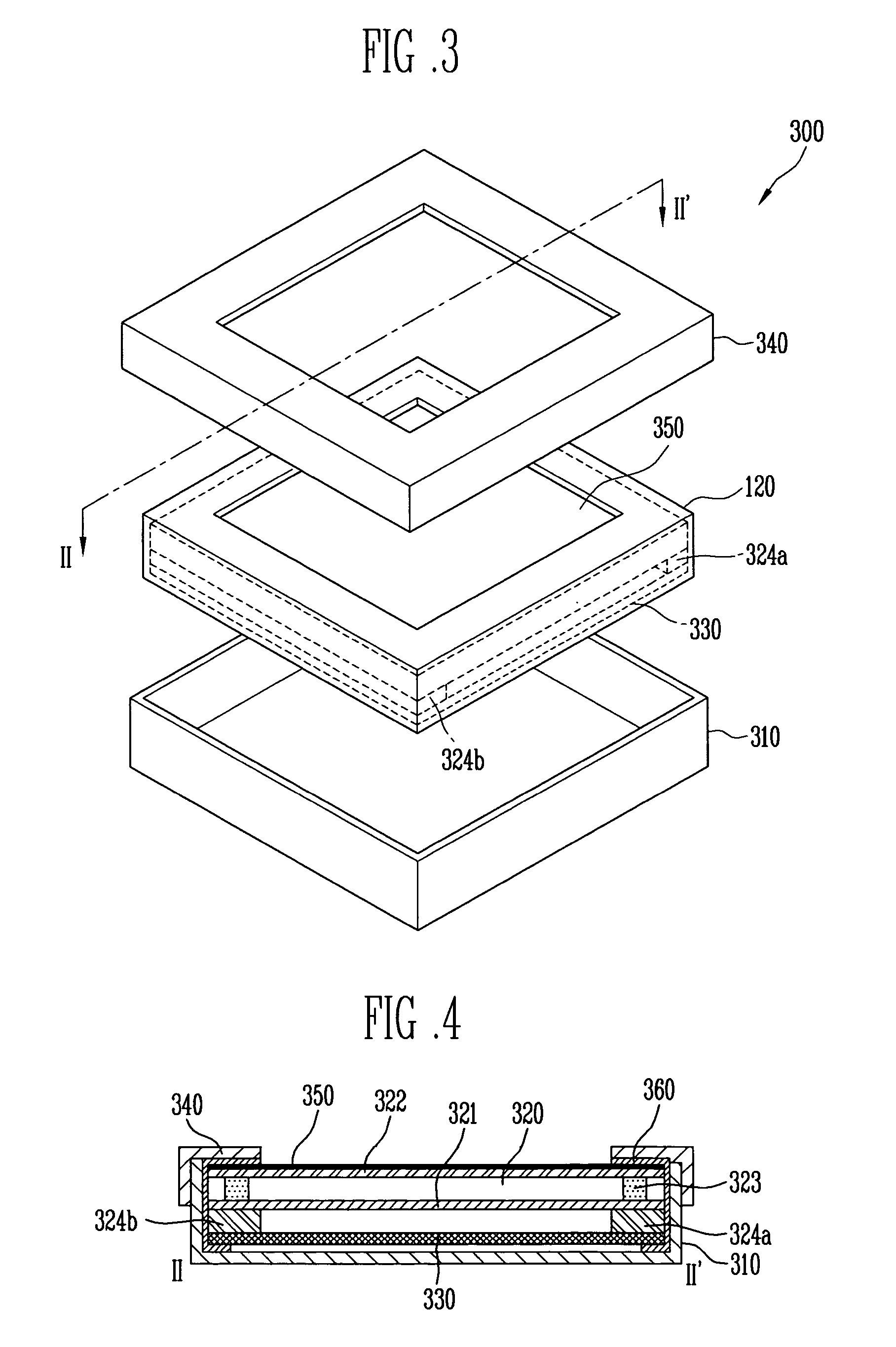
[0025]Referring to FIGS. 3 and 4, a flat panel display 300 having enhanced thermal dissipation uniformity according to the present invention includes an image display panel 320 wherein a first substrate 321 is spaced apart from a second substrate 322. A transparent conductive film 350 is formed on the front side of the image display panel. A chassis member 330 is positioned on the rear side of the image display panel 320. A conductive member 360 connects the transparent conductive film 350 and the chassis member 330.

[0026]In an exemplary embodiment, a bottom cover 310 fixes and surrounds the rear side and the outer portion of the image display panel 320 and a top cover 340 surrounds a front outer portion of the image display panel 320.

[0027]Referring now to FIG. 5, in the image display panel 320 the first substrate 321, which is an electron emission substrate, is spaced apart from the second substrate 322, which is an image forming substrate. A vacuum state is maintained between the...


PUM

PropertyMeasurementUnit
thermal dissipation uniformityaaaaaaaaaa
transparent conductiveaaaaaaaaaa
transparentaaaaaaaaaa

Abstract

A flat panel display is provided having enhanced thermal dissipation uniformity. The flat panel display includes an image display panel wherein a first substrate is spaced apart from a second substrate. A transparent conductive film is formed on the front side of the image display panel. A chassis member is positioned on the rear side of the image display panel. A conductive member connects the transparent conductive film and the chassis member.

Description

CROSS-REFERENCE TO RELATED APPLICATIONS[0001]This application claims priority to and the benefit of Korean Patent Application No. 2005-0104637, filed on Nov. 2, 2005, in the Korean Intellectual Property Office, the entire content of which is incorporated herein by reference.BACKGROUND[0002]1. Field of the Invention[0003]The present invention relates to a flat panel display, and more particularly to a flat panel display having enhanced thermal dissipation uniformity.[0004]2. Discussion of Related Art[0005]Flat panel displays such as a liquid crystal display (LCD), a plasma display panel (PDP) and, in particular, an electron emission display (EED) have been developed and put to practical use.[0006]The EED has been highlighted as a promising next generation display with regard to view angle, high speed response, high brightness, high definition and thinness.[0007]The EED is typically formed of in triode structure having a cathode electrode, an anode electrode and a gate electrode. More...

Claims


Application Information

Patent Timeline
Patent Type & Authority Patents(United States)
IPC IPC(8): G02F1/1333
CPCG02F1/133308G02F1/133385H01L51/529G02F2201/50G02F2001/133317G02F1/133317H01J17/28H01J11/34H10K50/87
Inventor CHOI, YOUNG KIL
Owner SAMSUNG SDI CO LTD
Learn More