Polarization lidar for the remote detection of aerosol particle shape

a lidar and aerosol particle technology, applied in the field of laser radars or lidars, can solve the problems of limited capabilities of current methods of remotely obtaining information about aerosol particles, the threat of intentional release of biological, chemical or radiological contaminants into the atmosphere, and the threat to civilian populations, so as to achieve the effect of safe dispersing the energy of beam components

Inactive Publication Date: 2009-08-25
UNIV FOR ATMOSPHERIC RES
View PDF24 Cites 63 Cited by
  • Summary
  • Abstract
  • Description
  • Claims
  • Application Information

AI Technical Summary

Benefits of technology

[0016]In accordance with another aspect of the present invention, a lidar system is provided where the transmission of an optical beam having a primary wavelength between about 1.5-1.8 microns is limited to laser light in a single polarization plane. This may be achieved by the use of a thin film plate polarizer in the transmitter that removes components of polarization that are not in the main polarization plane of the beam source. Beam components reflected from the thin film plate polarizer may be directed into a beam dump such as a black box or other optical absorber. The beam dump would be used to safely disperse the energy of the beam components reflected from the thin film plate polarizer. The highly polarized beam can also be directed through a Faraday isolator to prevent back

Problems solved by technology

In modern times the potential of intentional releases of a biological, chemical or radiological contaminants into the atmosphere is a real and serious threat to civilian populations in the United States and abroad and also to military personnel throughout the world.
Current methods of remotely obtaining information about aerosol particles are limited in their capabilities.
Due to the wavelengths used by known systems, this method is either no

Method used


Image

  • Polarization lidar for the remote detection of aerosol particle shape
  • Polarization lidar for the remote detection of aerosol particle shape
  • Polarization lidar for the remote detection of aerosol particle shape

Examples


Embodiment Construction

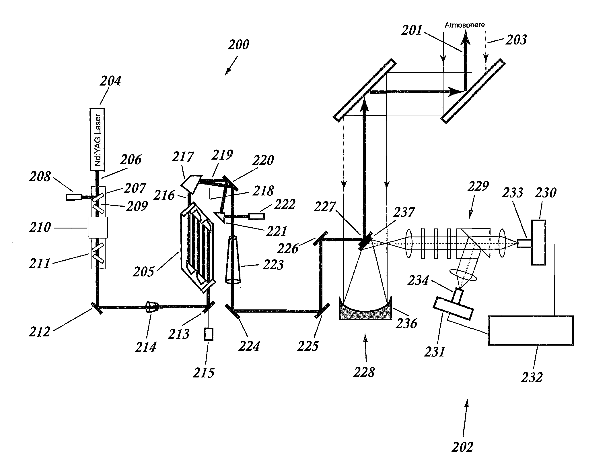
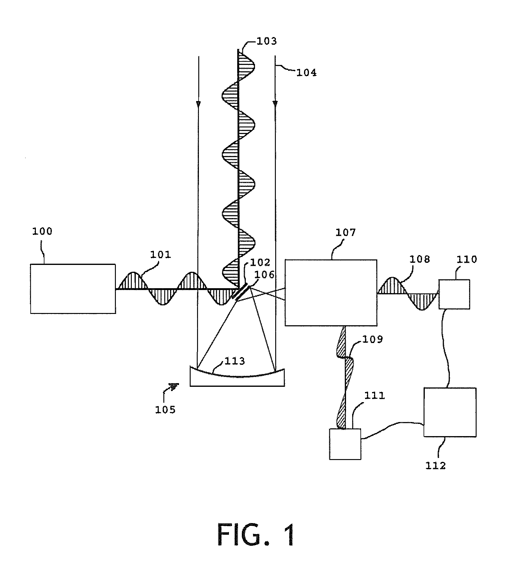
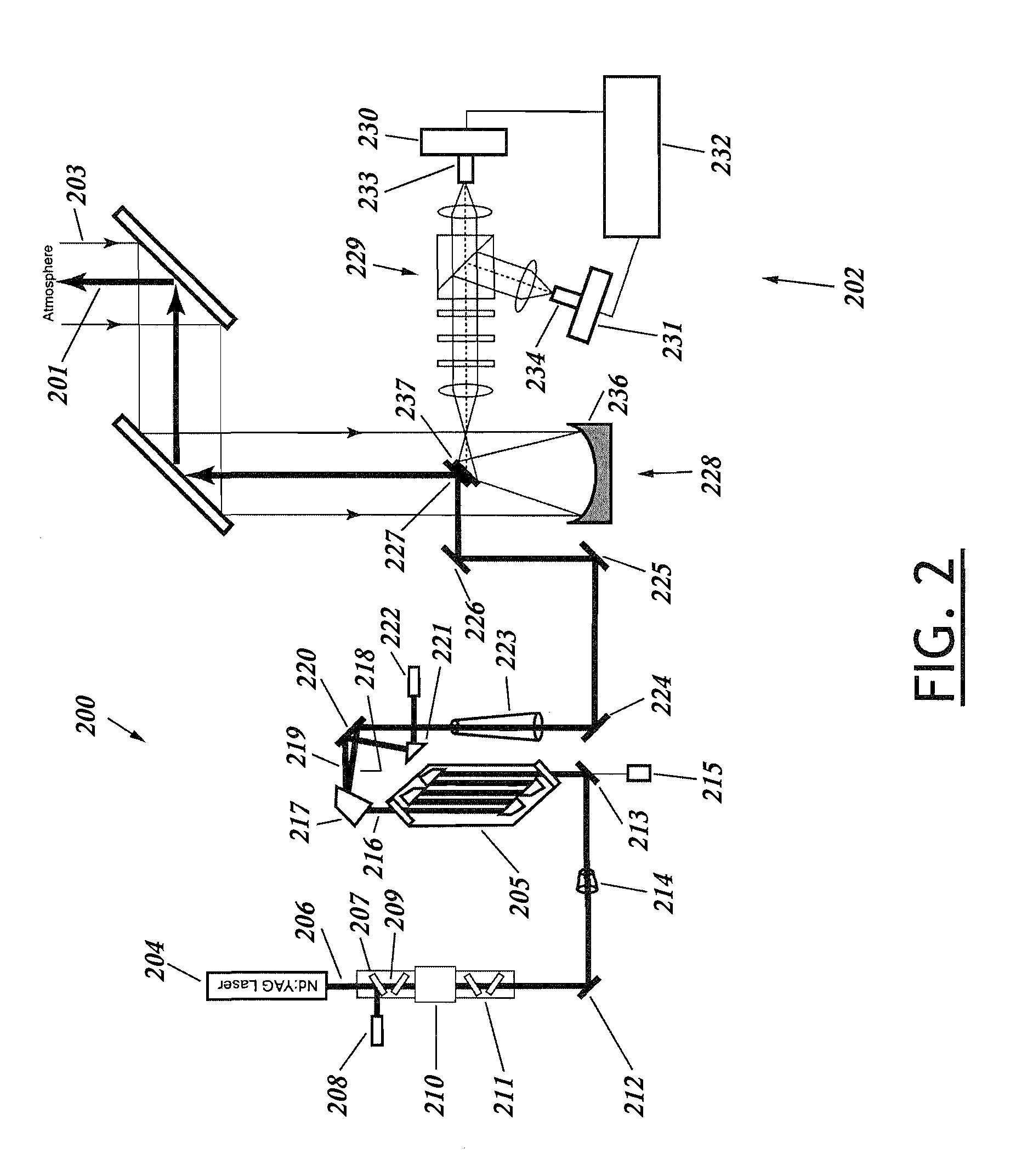
[0052]In the following description, an embodiment of the invention is set forth first in a high level depiction to describe the basic principles involved in using energy of a known polarization projected into the atmosphere to remotely determine aerosol particle characteristics. An embodiment of the invention is then described in detail in the context of a high pulse energy and Raman shifted Eye-safe Aerosol Lidar (REAL™) system which transmits single-plane linearly polarized energy and divides and separately detects polarized backscattered radiation in the same polarization plane as the transmitted beam and in a plane perpendicular to the polarization plane of the transmitted beam. Indeed, the invention has a number of benefits and provides useful results in this regard. A further embodiment involving multiple beams and selective induced fluorescence is then described. However, it will be appreciated that various aspects of the present invention are not limited to such lidar applic...


PUM


Abstract

A polarization lidar system capable of remotely identifying characteristics of atmospheric aerosol particles by transmitting a polarized beam of light and analyzing polarization characteristics of received backscatter is disclosed. The transmitter features high pulse energy to remotely identify aerosol particles with substantially one pulse. The transmitter employs a thin film plate polarizer and a Raman wavelength shifter to achieve eye-safe, single-plane linearly polarized energy. The transmit beam and receiver field of view are coaxial. The receiver employs a telescope, a collimating lens, and a beam splitter. The beam splitter splits the received backscatter into a single-plane polarized beam whose polarization plane is parallel to the plane of transmission and a single-plane polarized beam whose polarization plane is perpendicular to the plane of transmission. Each split beam is directed through separate focusing lenses onto separate detectors. The detector signals are amplified and processed to remotely determine atmospheric aerosol particle characteristics.

Description

GOVERNMENT SUPPORT[0001]The present invention was made with Government support under Cooperative Agreement No. ATM-0301213 awarded by the National Science Foundation. The Government has certain rights in this invention.FIELD OF THE INVENTION[0002]This invention relates to laser radars or lidars in general and more particularly to a lidar system suitable for defense, scientific, environmental and commercial applications requiring long range remote identification of aerosol particles.BACKGROUND OF THE INVENTION[0003]The remote identification of aerosol particles is critical in many different applications. Of primary importance is the remote identification of chemical, radiological or biological agents in the atmosphere. In modern times the potential of intentional releases of a biological, chemical or radiological contaminants into the atmosphere is a real and serious threat to civilian populations in the United States and abroad and also to military personnel throughout the world. It...

Claims


Application Information

Patent Timeline
IPC IPC(8): G01N21/00
CPCG01N21/21G01S17/95G01S7/499G01N2021/1793G01N2021/4792G01N2021/4709Y02A90/10
Inventor MAYOR, SHANESPULER, SCOTT
Owner UNIV FOR ATMOSPHERIC RES
Why Eureka
Try Eureka