Data migration using temporary volume to migrate high priority data to high performance storage and lower priority data to lower performance storage

a data migration and temporary volume technology, applied in the direction of fault response, instruments, sustainable buildings, etc., can solve the problems of a large amount of data evaluation, a long time to migrate data, and the value of data is not fixed

Inactive Publication Date: 2009-08-25
HITACHI LTD
View PDF6 Cites 27 Cited by
  • Summary
  • Abstract
  • Description
  • Claims
  • Application Information

AI Technical Summary

Benefits of technology

[0009]The present invention was conceived in view of the above problems and an object of the present invention is to provide a storage control device and a data migration method for the storage control device that make it possible to improve user convenience with respect to data migration. A further object of the present invention is to provide a storage control device and a data migration method for the storage control device that makes it possible to improve user convenience and shorten the data migration time by moving at least a portion of the data in advance by using a temporary volume that is pre-prepared in each volume group before data migration is determined. Yet another object of the present invention is to provide a storage control device and a data migration method for the storage control device that makes it possible to improve user convenience which is able to automatically judge the value of data and move data in a relatively short time to a logical volume that depends on the value of the data. Further objects of the present invention will become evident from the following description of the embodiments.

Problems solved by technology

However, the value of data is not fixed and the evaluation of a lot of data drops as time elapses.
Hence, although there is also variation depending on the total size of the data constituting the migration target, it takes a long time until the data migration is complete and user convenience is low.

Method used


Image

  • Data migration using temporary volume to migrate high priority data to high performance storage and lower priority data to lower performance storage
  • Data migration using temporary volume to migrate high priority data to high performance storage and lower priority data to lower performance storage
  • Data migration using temporary volume to migrate high priority data to high performance storage and lower priority data to lower performance storage

Examples


first embodiment

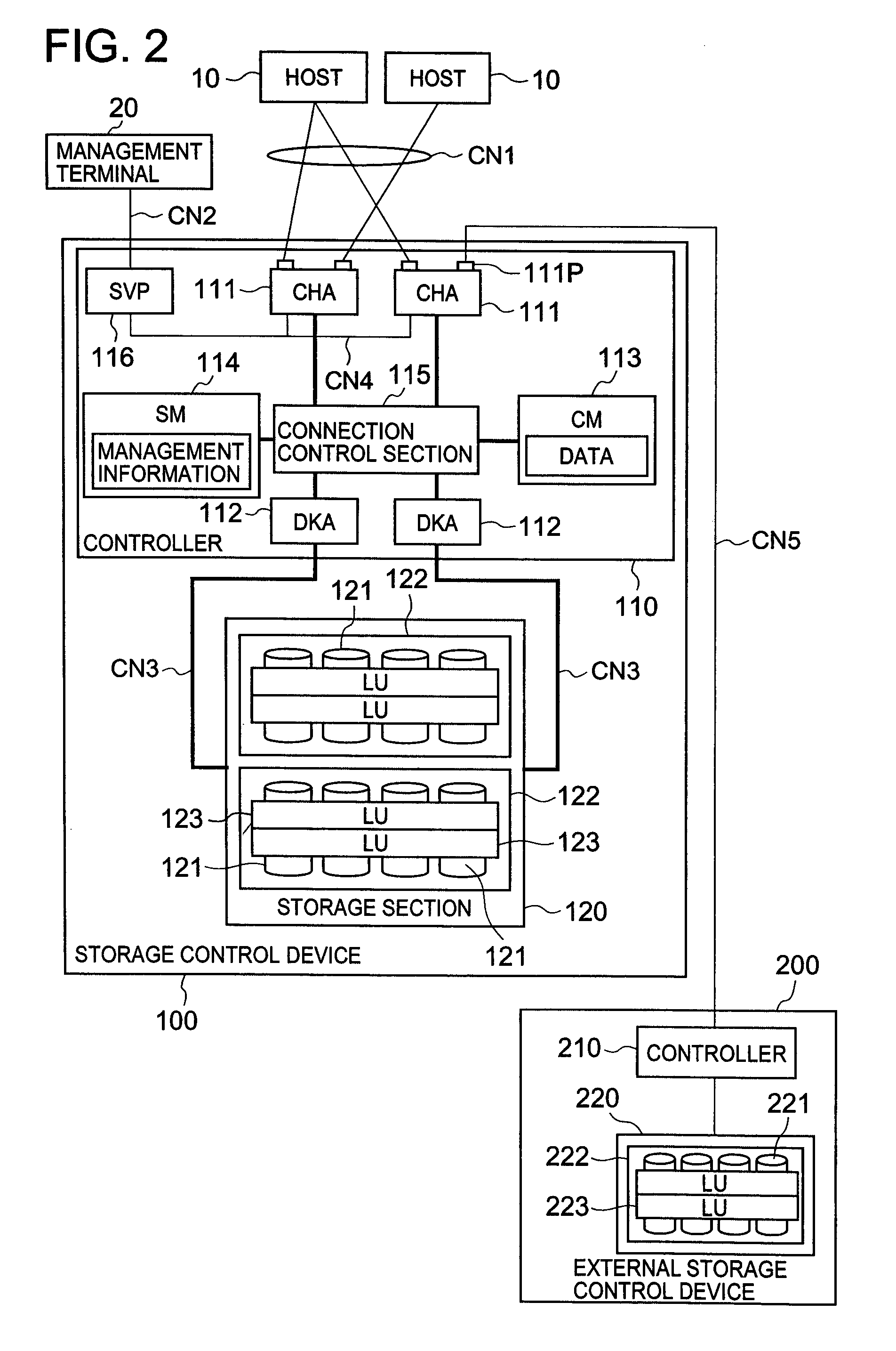
[0086]FIG. 2 is a block diagram that shows the constitution of the important parts of the storage control device of this embodiment. A host 10 is, for example, a computer device that comprises information processing resources such as a CPU (Central Processing Unit) and memory and so forth, and is constituted as a personal computer, work station, server computer, or mainframe computer, or the like, for example.

[0087]The host 10 comprises a communication control section for accessing a storage control device 100 via a communication network CN1, and an application program such as database software, for example.

[0088]Depending on the case, a LAN (Local Area Network), a SAN (Storage Area Network), the Internet, a dedicated line, a public line, or the like, for example, can be suitably used as the communication network CN1. Data communications via a LAN are performed in accordance with the TCP / IP protocol, for example. When the host 10 is connected to the storage control device 100 via th...

second embodiment

[0179]The second embodiment of the present invention will now be described on the basis of FIGS. 15 and 16. The subsequent embodiments that include this embodiment correspond to modified examples of the first embodiment above. In this embodiment, the supply of power to the external storage control devices 200 is stopped by setting the external volumes 223 provided by the external storage control devices 200 to an offline state as far as is possible and the power consumption amount of the whole storage system is reduced.

[0180]FIG. 15 is an explanatory diagram that shows an aspect in which volumes in an offline state are grouped in the external storage control devices 200 and the power supply to the external storage control devices 200 is stopped. As shown in FIG. 15A, the volume group 130 is constituted by logical volumes 123(1) to 123(3) corresponding to the external volumes 223(1) to 223(3).

[0181]The external volume 223(1) of the first external storage control device 200 (1) corres...

third embodiment

[0195]A third embodiment will now be described with respect to FIGS. 17 to 23. In this embodiment, a temporary volume is used to create a backup of the backup-target volume beforehand before a backup instruction is issued.

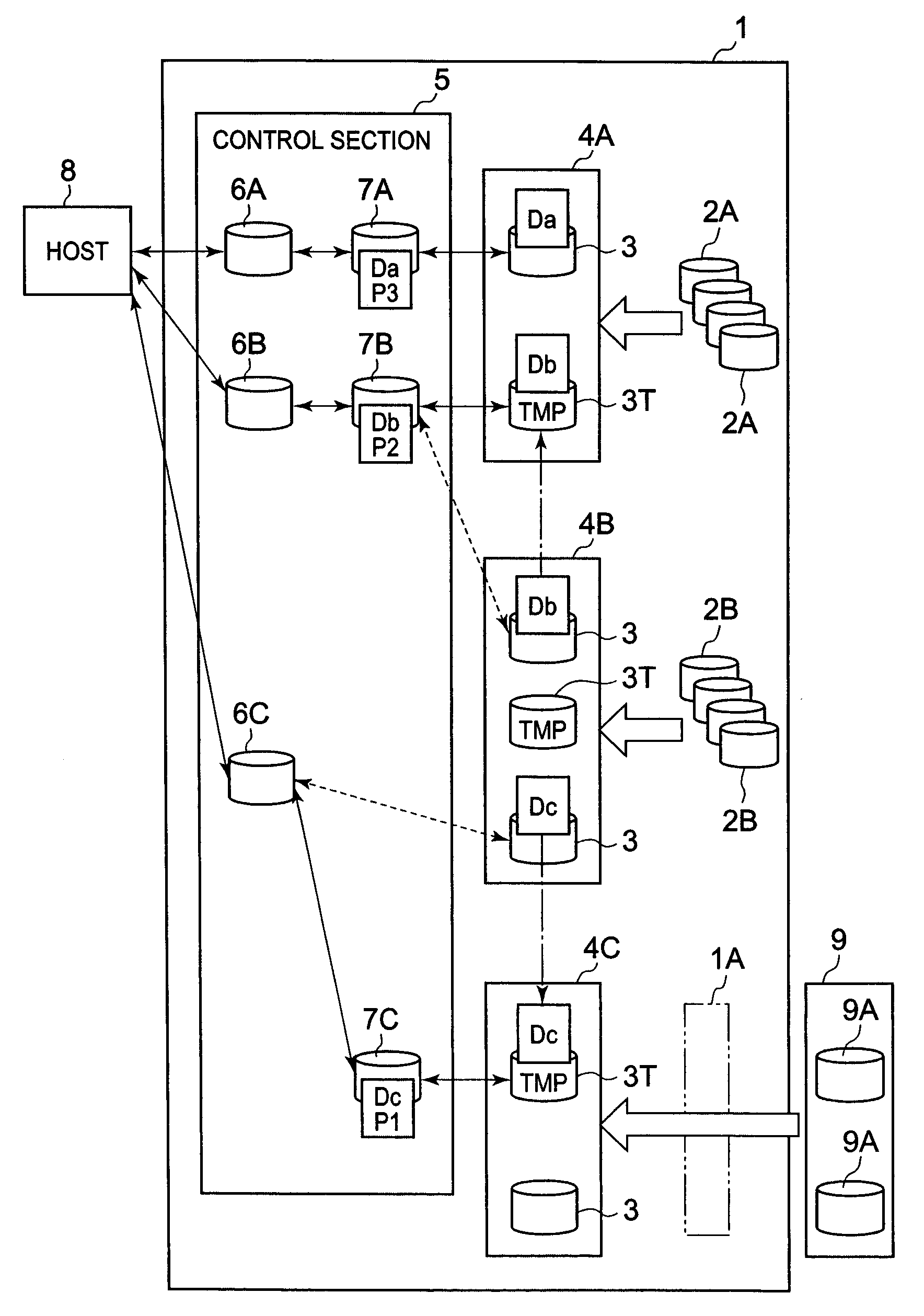
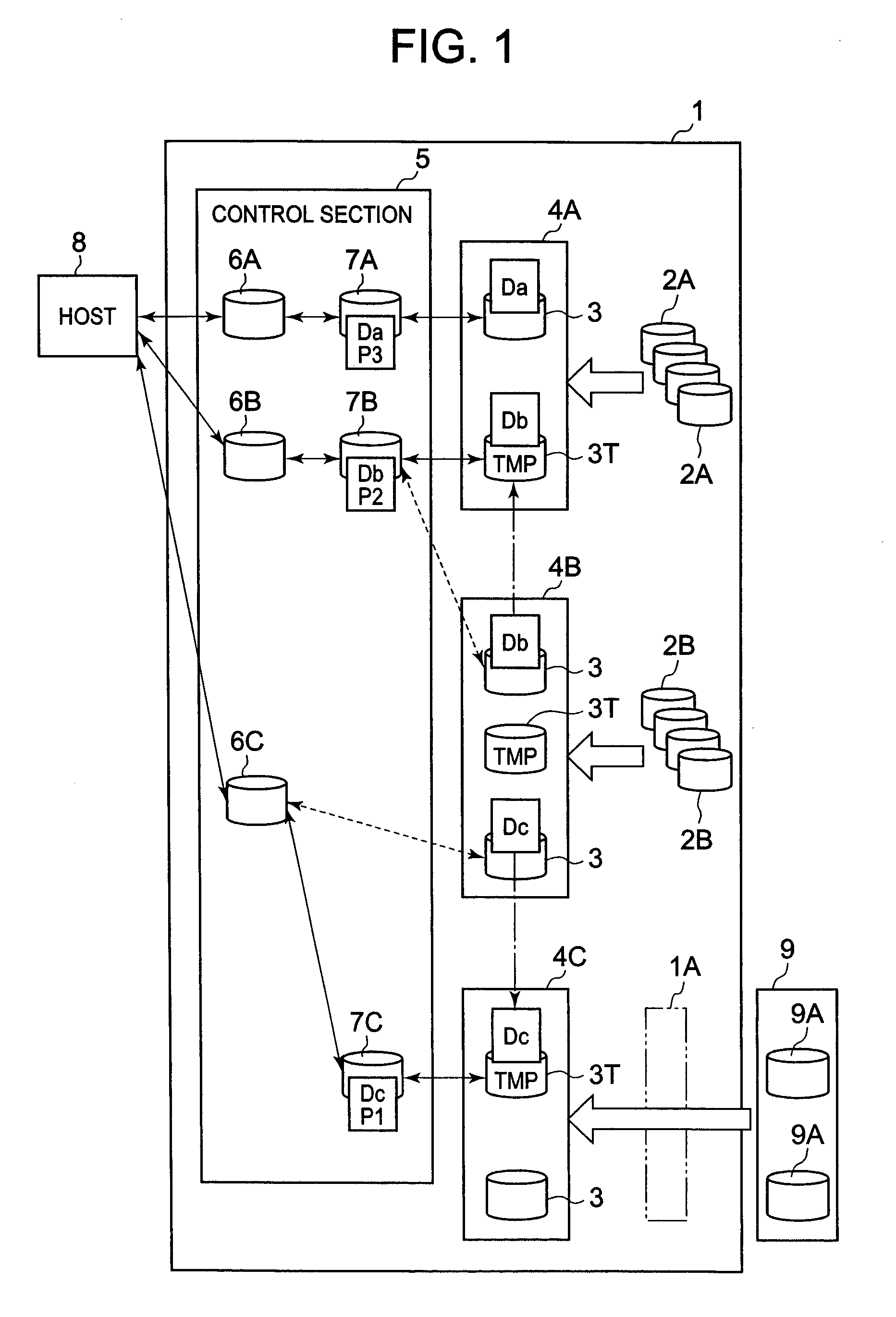
[0196]FIGS. 17 to 22 are explanatory diagrams of an aspect in which backup target data Da which are stored in the primary volume 123 (A1) are backed up automatically and stepwise. The primary volume 123 (A1) used by the host 10 is made to correspond with the access point 151 (1) by means of the management volume 152 (1). The initial priority level of the data (operating data) Da of the backup target is assumed to be “1”.

[0197]As shown in FIG. 18, the controller 110 copies data Da from the primary volume 123 (A1) to temporary volume 123 (B1) provided in lower volume group 130B which is one volume group lower when a time comes when the host 10 is not accessing data Da. The management volume 152(2) for managing the data copied to the temporary volume 123 (B1) then man...


PUM


Abstract

The storage control device of the present invention uses a temporary volume to move data rapidly between volume groups. The storage control device forms a plurality of volume groups by grouping volumes of the same performance. At least one or more temporary volumes are each pre-provided in the respective volume groups. The control section calculates and manages the priority levels of the respective data. The data with the highest priority level in the lower volume group are copied beforehand to the temporary volume in the upper volume group at a time when the data are not being accessed by the host. As a result, data can be moved rapidly when data migration is executed and so forth.

Description

CROSS-REFERENCE TO RELATED APPLICATIONS[0001]This application relates to and claims priority from Japanese Patent Application No. 2006-294300 filed on Oct. 30, 2006, the entire disclosure of which is incorporated herein by reference.BACKGROUND OF THE INVENTION[0002]1. Field of the Invention[0003]The present invention relates to a storage control device and a data migration method for the storage control device.[0004]2. Description of the Related Art[0005]In government, government administration offices, local self-governing bodies, enterprises, and educational institutions, and so forth, for example, data are managed by using relatively large-scale storage systems to handle large quantities of data of a variety of types. Such storage systems are constituted by a storage control device such as a disk array device. The disk array device is constituted by providing a multiplicity of disk drives in the form of an array and provides a RAID (Redundant Array of Independent Disks)-based sto...

Claims


Application Information

Patent Timeline
Patent Type & Authority Patents(United States)
IPC IPC(8): G06F12/00G06F11/00G06F13/00G06F13/28G06F3/06
CPCG06F3/0613G06F3/0625G06F3/0634G06F3/0689G06F3/0649G06F11/1448Y02B60/1246Y02D10/00
Inventor MIYAGAKI, ATSUSHIYASUTA, KOJI
Owner HITACHI LTD
Why Eureka
Try Eureka