Method for operating an internal combustion engine

a technology of internal combustion engine and fuel consumption, which is applied in the direction of electric control, charge feed system, fuel injection apparatus, etc., can solve the problems of low emissions and achieve favorable effect on the fuel consumption of the internal combustion engine, low emissions, and favorable fuel consumption in the internal combustion engin

Inactive Publication Date: 2009-09-01
ROBERT BOSCH GMBH
View PDF6 Cites 30 Cited by
  • Summary
  • Abstract
  • Description
  • Claims
  • Application Information

AI Technical Summary

Benefits of technology

[0004]The present invention allows compensation for a disadvantageous temperature loss in a shut off cylinder by brief and possibly repeated “heating operation.” A shut off cylinder thus cools down less during the cylinder shut off period. When the cylinder shut off period ends, good mixture preparation is possible in the “preheated” cylinder which is now operating again, which in turn results in low emissions and a favorable fuel consumption in the internal combustion engine. Due to the at least essentially torque-neutral combustion of the fuel, the measure according to the present invention does not affect or at least does not detectably affect the comfort in the operation of the internal combustion engine, and without the cylinders which are not shut off having to depart from the optimal operating point for efficiency (high load). This has a favorable effect on the fuel consumption of the internal combustion engine. It is noted here that the method according to the present invention not only provides advantages during half-engine operation, but rather also during overrun fuel cutoff, for example, and the method according to the present invention may be used both in internal combustion engines having intake-manifold fuel injection and also in internal combustion engines having direct fuel injection.
[0005]In a preferred refinement of the method according to the present invention, fresh combustion air is introduced into the at least one shut off cylinder during the cylinder shut off period only in connection with the operating cycle(s) during which fuel is combusted. The work connected with the charge change is thus saved or at least reduced during a majority of the cylinder shut off period, and as much residual gas as possible may remain enclosed in the cylinder, which is also advantageous. The work needed for dragging along the shut off cylinder is thus reduced and the cooling of the corresponding cylinder combustion chamber is reduced via the resulting higher temperature level.
[0007]The additional fuel consumption due to the injection during the cylinder shut off period is minimal if precisely enough fuel and / or air is introduced into the cylinder, which is shut off per se, to at least approximately compensate, by the combustion of the fuel, for the pressure and / or temperature loss which occurred during preceding operating cycles since the last combustion. This may be implemented easily by opening the at least one intake valve of the at least one shut off cylinder for a significantly shorter time than a corresponding intake stroke lasts.
[0008]It is also suggested that at least one exhaust valve of the at least one shut off cylinder remain continuously closed during the cylinder shut off period. Therefore, a maximum residual gas quantity remains in the cylinder combustion chamber, which in turn minimizes the work needed for dragging along the shut off cylinder and the temperature loss.
[0009]In an advantageous refinement of the method according to the present invention, the instant of injection and / or combustion of fuel into the at least one shut off cylinder is made as a function of a temperature of the internal combustion engine and / or a number of operating cycles since the last combustion and / or a current engine speed. This ensures that the temperature and / or pressure of the internal combustion engine is held as accurately as possible at a desired level, without an unnecessarily large number of injections being necessary, which would unnecessarily worsen the fuel consumption and the emission behavior.

Problems solved by technology

When the cylinder shut off period ends, good mixture preparation is possible in the “preheated” cylinder which is now operating again, which in turn results in low emissions and a favorable fuel consumption in the internal combustion engine.

Method used


Image

  • Method for operating an internal combustion engine
  • Method for operating an internal combustion engine
  • Method for operating an internal combustion engine

Examples


Embodiment Construction

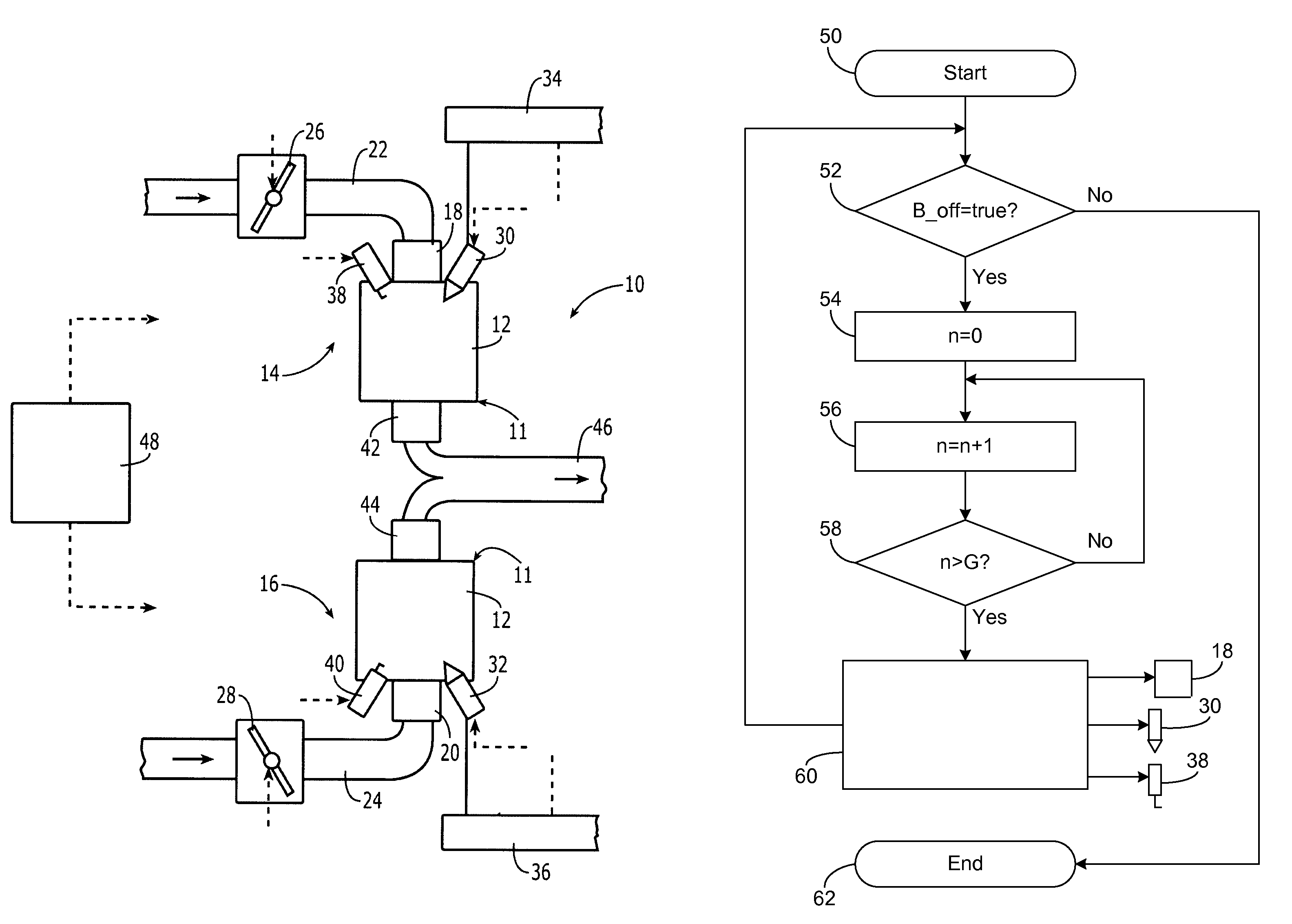
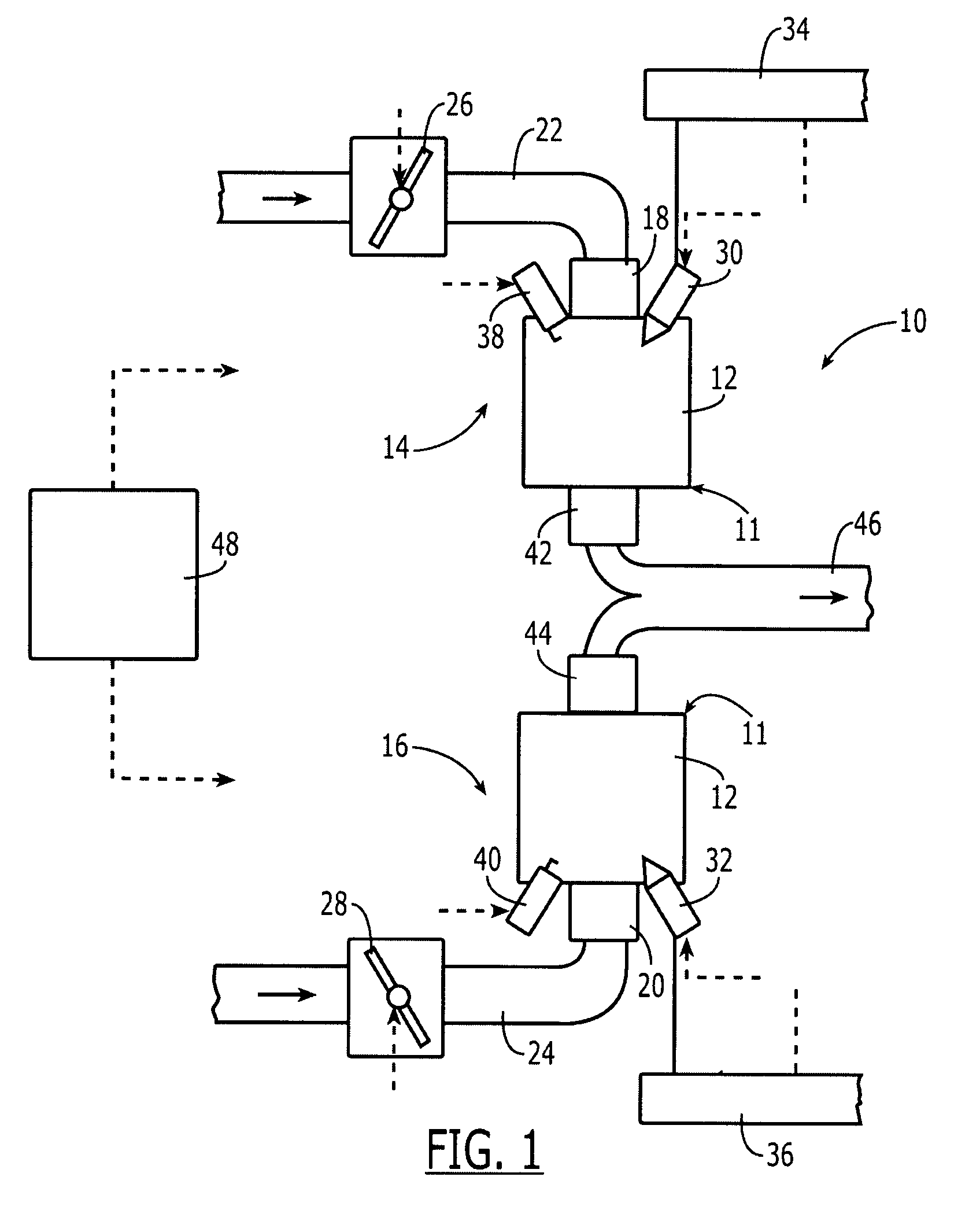
[0013]An internal combustion engine carries reference numeral 10 as a whole in FIG. 1. It is used for driving a motor vehicle (not shown in FIG. 1). Internal combustion engine 10 includes multiple cylinders 11 having combustion chambers 12, of which only two are shown in FIG. 1 for the sake of simplicity. The totality of cylinders 11 is composed of a first partial set 14 of cylinders 11 and a second partial set 16 of cylinders 11. If a total of eight cylinders 11 are assumed, for example, first partial set 14 may include four cylinders 11 and second partial set 16 may also include four cylinders 11.

[0014]Combustion air reaches combustion chambers 12 in each case via an intake valve 18 or 20 and an intake manifold 22 or 24, respectively. A throttle valve 26 or 28 is situated in each intake manifold 22 or 24 belonging to a partial set 14 or 16, respectively. Fuel reaches combustion chambers 12 in each case directly via injectors 30 and 32. However, the following statements may also be...


PUM


Abstract

An internal combustion engine includes multiple cylinders. A partial set of the cylinders may be temporarily shut off. Fuel is introduced briefly into at least one of the shut off cylinders and combusted in an at least essentially torque-neutral way during the cylinder shut off period.

Description

BACKGROUND INFORMATION[0001]The overall efficiency of internal combustion engines, as they are currently used in motor vehicles, is typically maximal at those operating points which are close to full load and at low to moderate engine speeds. In partial-load operation, the energy contained in the fuel is not optimally utilized. As a result, the fuel consumption is higher than would be necessary per se. However, such partial-load operation is the normal operation in motor vehicles having high-performance internal combustion engines.[0002]One may attempt to keep the operating point in the range of optimum efficiency as continuously as possible via an optimum design of manual shift transmissions and shifting strategies in automatic transmissions, for example, having a continuous transmission ratio. Another possibility is the concept of so-called “half-engine operation” in which one part of the cylinders operates at a comparatively high load and thus at a comparatively good efficiency. ...

Claims


Application Information

Patent Timeline
Patent Type & Authority Patents(United States)
IPC IPC(8): F02D7/00F02D17/04
CPCF02D41/0087F02D35/02F02D13/06F02D17/02
Inventor SCHULZ, TORSTEN
Owner ROBERT BOSCH GMBH
Why Eureka
Try Eureka