Infinitely variable transmission with power branching, with electric selector

a transmission and variable technology, applied in the direction of electric propulsion mounting, electric gearbox mounting, transportation and packaging, etc., can solve the problems of difficult matching to the type of engine, whether it be gasoline or diesel, and the torque jolts that are sensed as unpleasant by users, so as to achieve the effect of reducing the operating speed of the gearbox and easy adjustmen

Inactive Publication Date: 2009-09-01
RENAULT SA
View PDF20 Cites 19 Cited by
  • Summary
  • Abstract
  • Description
  • Claims
  • Application Information

AI Technical Summary

Benefits of technology

[0024]The mode-changing system can be disposed on the periphery of the gearbox, in such a way that it can be adjusted more easily by means of hydraulic actuators or electromechanical actuators.
[0025]Finally, the operating speeds of the gearbox can be reduced by the adopted transmission structure.

Problems solved by technology

Nevertheless, in these known two-mode architectures, the mode changes are effected by multiple-disk clutches disposed on the output of the transmission, and for this reason are accompanied by torque jolts that are sensed as unpleasant by the users.
Another disadvantage of the architectures described in these patents lies in their complexity, in particular related to the presence of at least two clutches and one brake.
Application of these prior art teachings poses the problem of an infinitely variable transmission (I.V.T.) that is sufficiently compact that it can be disposed easily in a motive power unit of a vehicle.
In addition, such an infinitely variable transmission is difficult to use with an internal combustion engine that produces high torque and power, and it cannot be easily matched to the type of engine, whether it be gasoline or diesel.
The prior art leads to design problems for the hydraulic actuation circuit, which then poses major problems during repair and maintenance of the gearbox, particularly in the case in which the mode-changing system is constructed in the form of a multiple-disk clutch.
In the case in which the mode-changing system is provided with mechanical gearbox claws, there are problems for exchanging the mode-changing system inside the gearbox.
Finally, the matching of such a gearbox to a gasoline-powered internal combustion engine also poses a problem related to the speeds of rotation, which are very high, thus imposing large mechanical stresses on certain spinning elements.

Method used


Image

  • Infinitely variable transmission with power branching, with electric selector
  • Infinitely variable transmission with power branching, with electric selector
  • Infinitely variable transmission with power branching, with electric selector

Examples


Embodiment Construction

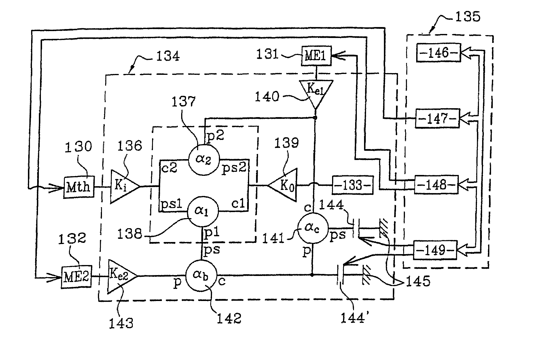
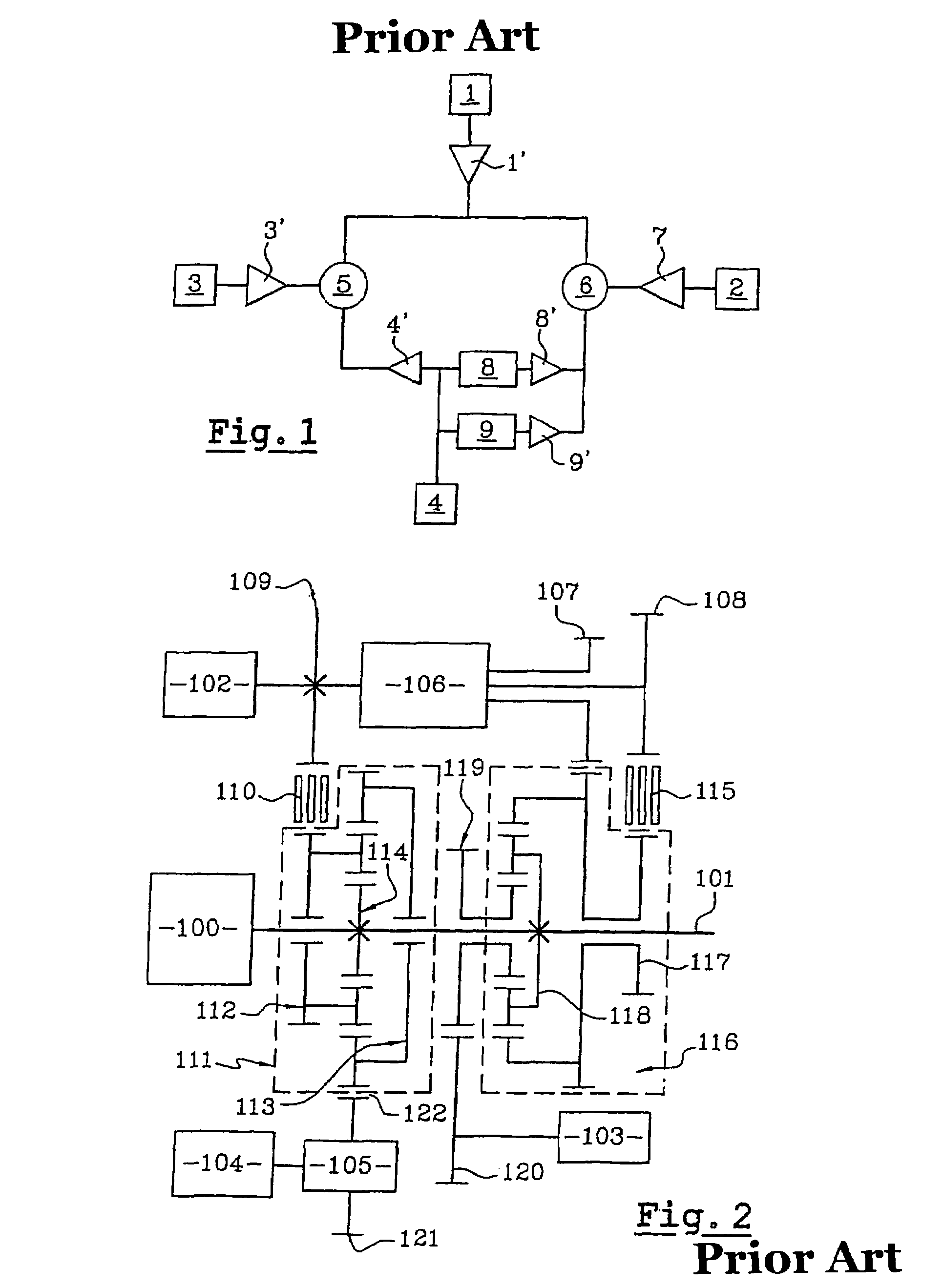
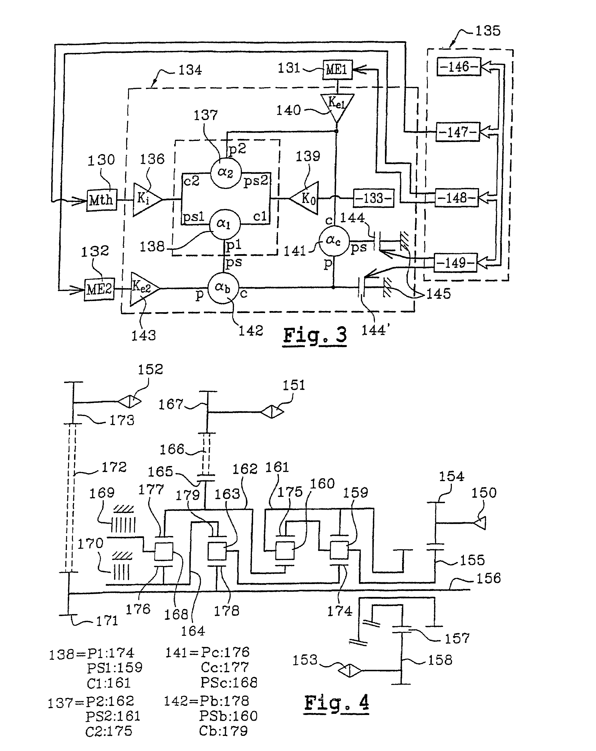
[0036]FIG. 1 illustrates the basic diagram of the infinitely variable transmission of French Patent Application 01.04690.

[0037]The transmission of FIG. 1 is composed of two epicyclic gearsets 5, 6, seven reducing stages 7, two mode-changing systems 8 and 9, which can be either claw couplings or multiple-disk clutches, and two electric machines 2, 4, together comprising a variator.

[0038]This transmission has four input and output connections, which can be connected respectively to internal combustion engine 1, to wheels 3 and to the two electric machines 2 and 4.

[0039]Internal combustion engine 1 is connected to a reducing stage 1′. Wheels 3 are connected to two reducing stages 3′. A first electric machine 2 of the variator is connected to a reducing stage 7 and a second electric machine 4 is connected to a reducing stage 4′ and to two mode-changing systems 8 and 9.

[0040]Three reducing stages are connected to first epicyclic gearset 5. Four reducing stages are connected to second epi...


PUM


Abstract

An infinitely variable transmission with power shunting having at least two operating modes, whereof the components are distributed between two power paths connecting in parallel the heat engine to the vehicle wheels, including at least three planetary gear trains, two electrical machines, at least one reduction stage, and a control distributing differently the power between the two power paths based on the operating mode thereof.

Description

BACKGROUND OF THE INVENTION[0001]I. Field of the Invention[0002]The present invention relates to a power-splitting transmission, by means of which there can be achieved a continuous variation from reverse gear to forward gear, passing through a particular position referred to as “neutral engaged”, wherein the travel speed of the vehicle is zero for any speed whatsoever of the internal combustion engine.[0003]More precisely, its object is a power-splitting infinitely variable transmission on the basis of an electric variator and of a compound gearset, plus adjusting means that distribute the power between the input and output of the transmission differently depending on the mode of operation thereof.[0004]II. Description of Related Art[0005]Power-splitting transmissions can be based on three known principles or modes of power splitting. According to the first mode, known as “coupled-input”, the transmission is provided with a pair of power-splitting pinions for splitting the power at...

Claims


Application Information

Patent Timeline
Patent Type & Authority Patents(United States)
IPC IPC(8): F16H3/72B60K1/02B60K6/365B60K6/38B60K6/40B60K6/42B60K6/445B60L50/16
CPCB60K6/365B60K6/38B60K6/40B60K6/42B60K6/445F16H3/728B60W20/20B60W20/00B60K1/02Y02T10/6239F16H2200/2007F16H2200/201F16H2200/2012Y02T10/62F16H3/44B60W2710/18B60W2710/02B60W10/101B60W2510/10B60W10/02
Inventor KEFTI-CHERIF, AHMEDPICARD, MARCBUANNEC, MICHELCHANSON, SEBASTIEN
Owner RENAULT SA
Why Eureka
Try Eureka