Injection molding method and injection molding apparatus

a technology of injection molding and injection molds, which is applied in the field of injection molding technologies, can solve the problems of shrinkage becoming a problem, large and expensive injection molds, and large injection molds

Active Publication Date: 2009-09-01
TOYOTA JIDOSHA KK
View PDF14 Cites 6 Cited by
  • Summary
  • Abstract
  • Description
  • Claims
  • Application Information

AI Technical Summary

Benefits of technology

[0009]The present invention reduces pressure necessary to apply to the resin within the cavity. Therefore, the pressure resistance required of the injection mold is reduced. As a result, the injection mold can be downsized, and the injection molding cost can be reduced.
[0012]This injection molding method obtains a synergistic effect by using both the technology that the back surface of the molded product separates from the cavity surface before the design surface of the molded product separates from the cavity surface, and the technology that pressure is continuously applied to the molten resin from the gate. The step of injecting the fluid from the flow channel is one of steps of guaranteeing that the back surface of the molded product will separate from the cavity surface before the design surface of the molded product separates from the cavity surface, and another step may be used instead of the fluid injecting step.

Problems solved by technology

For example, to form an automobile bumper, it is necessary to continue applying pressure of around 16 MPa to terminal areas (areas that are distant from the gate) where shrinkage can become a problem.
The large and expensive injection mold is required.

Method used


Image

  • Injection molding method and injection molding apparatus
  • Injection molding method and injection molding apparatus
  • Injection molding method and injection molding apparatus

Examples


embodiment 1

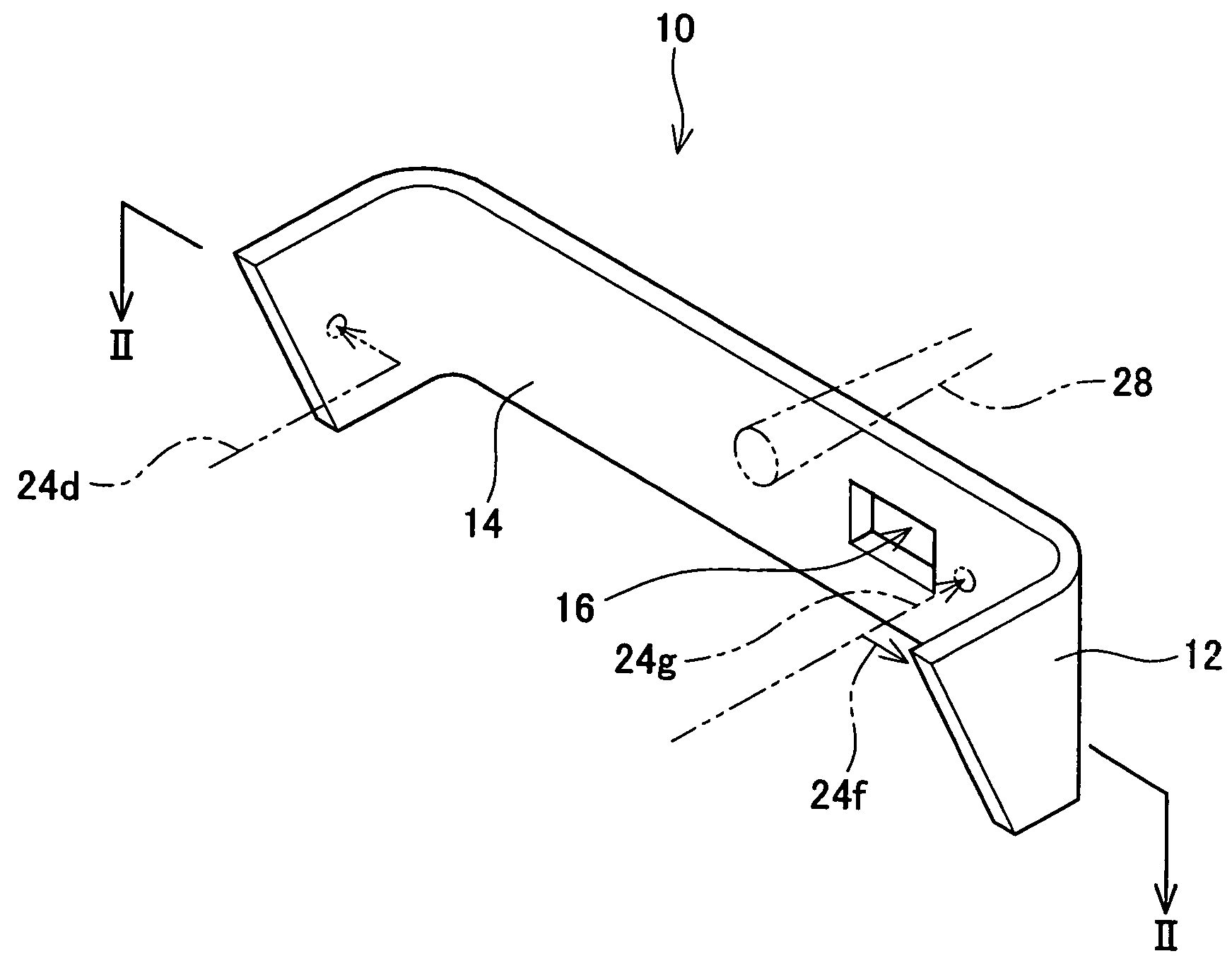
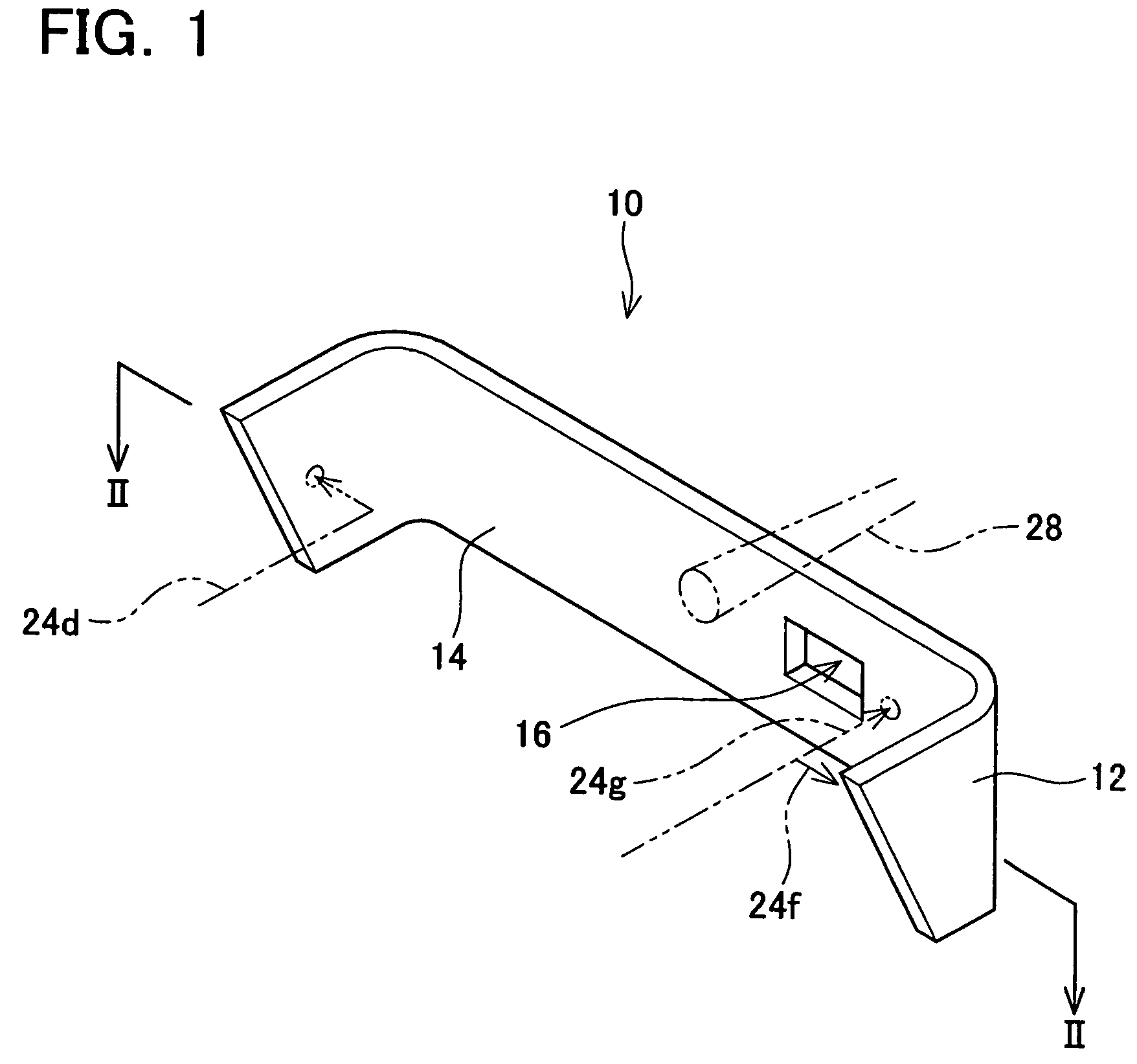
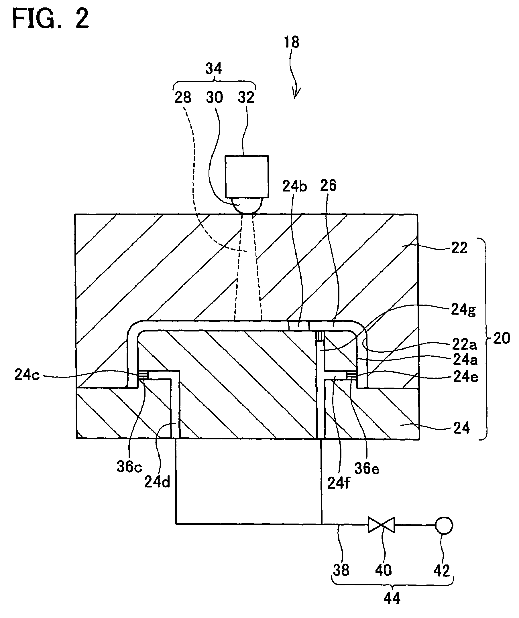
[0057]Embodiment 1 is explained below, referencing to the drawings. FIG. 1 is a perspective diagram of a molded product that is formed using the injection molding technology of the present embodiment. FIG. 2 is a schematic cross-sectional diagram of the injection molding apparatus of the present embodiment. FIG. 3 is a diagram that compares the injection molding method of the present embodiment with a conventional injection molding method. FIG. 4 is a process diagram for the injection molding method of the present embodiment. FIG. 5 is a diagram that illustrates the pressure necessary in the injection molding method of the present embodiment in comparison with that in a conventional example.

[0058]The molded product 10 illustrated in FIG. 1 is a molded resin product that is injection-molded by the injection molding apparatus 18 illustrated in FIG. 2. A typical example is a molded resin bumper for an automobile.

[0059]In the molded product 10, one surface 12 is a design surface (front ...

embodiment 2

[0084]Embodiment 2 is explained below, referencing the drawings. In Embodiment 2, an injection molding apparatus 50 illustrated in FIG. 6 is used to mold the molded product 10 having the same shape as in Embodiment 1 (see FIG. 1). The injection molding apparatus 50 comprises a mold 51 and a pressurizer 52. FIG. 6 shows only the part of the mold 51 that molds a terminal area of the molded product 10. The mold 51 comprises a female mold 53 and a male mold 54. The male mold 54 has a core 59. A cavity 55 is formed by combining the female mold 53 and the male mold 54. The cavity surface 56 of the female mold 53 corresponds to the design surface 12 of the molded product 10. The cavity surface 57 of the male mold 54 approximately matches the back surface 14 of the molded product 10. To open the mold 51, the female mold 53 and the male mold 54 are pulled apart vertically.

[0085]A fluid injection flow channel 58 is formed in the male mold 54. One end of the fluid injection flow channel 58 ope...


PUM

PropertyMeasurementUnit
pressureaaaaaaaaaa
pressureaaaaaaaaaa
pressureaaaaaaaaaa

Abstract

This invention relates to an injection molding method using an injection mold. The method comprises (1) a molten resin injection step for injecting the molten resin from a gate into a cavity, (2) a pressure-keeping step for continuously applying pressure from the gate after the molten resin injection step, and (3) a fluid injection step for injecting a fluid toward the back surface of the molded product. The pressure-keeping step and the fluid injection step are simultaneously executed.Simultaneously executing these two steps can lower the pressure that is to be continuously applied from the gate. The present injection molding method can reduce the pressure of the fluid to be injected toward the back surface of the molded product in order to cause the back surface of the molded product to separate from the cavity surface.

Description

TECHNICAL FIELD[0001]The present invention relates to injection molding technologies.[0002]The present application claims priority to Japanese Patent Application No. 2004-170400 filed on Jun. 8, 2004 and Japanese Patent Application No. 2004-373751 filed on Dec. 24, 2004, the contents of which are hereby incorporated by reference.BACKGROUND ART[0003]An injection mold is provided with a gate and a cavity connected with the gate. A molten resin is injected into the cavity from the gate. When the injected molten resin has solidified in the cavity, the mold is opened to remove a molded product from the mold.[0004]Resin shrinks when it solidifies. When the molten resin that has been filled in the cavity shrinks during solidification, the external shape of the molded product no longer matches the shape of the cavity. It is impossible to form the molded product into the desired external shape.[0005]To solve this problem, the following technology was developed. This technology continues to a...

Claims


Application Information

Patent Timeline
Patent Type & Authority Patents(United States)
IPC IPC(8): B29C44/02B29C45/00B29C45/17B29C45/26
CPCB29C45/174B29C45/0025B29C45/2628B29C45/17B29C45/77B29C45/43B29C45/00
Inventor UCHIDA, HIROSHITAKAHARA, TADAYOSHIETO, TOMOAKI
Owner TOYOTA JIDOSHA KK
Why Eureka
Try Eureka