Extendable rotor blades for power generating wind and ocean current turbines within a module mounted atop a main blade

a technology of extension rotor and turbine, which is applied in the direction of mechanical energy handling, mechanical equipment, machines/engines, etc., can solve the problems of large chord, inability to address the requirements of wind or ocean current applications, and inability to address the bielawa patent, so as to avoid fatigue failure, facilitate maintenance, and avoid the effect of weakening the main blade structur

Inactive Publication Date: 2009-09-01
UNITED TECH CORP
View PDF54 Cites 58 Cited by
  • Summary
  • Abstract
  • Description
  • Claims
  • Application Information

AI Technical Summary

Benefits of technology

[0036]The invention has the advantage that it is lightweight, easily maintainable, and durable, that will not weaken the main blade structure.
[0037]The invention has the advantage that extendable rotor blades are capable of being retrofitted to existing blade structures.
[0038]The invention has the advantage that the extendable rotor blades may be supported by the ribs and spars that strengthen the main rotor blades.
[0039]The invention has the advantage that if the extendable rotor blades are supported by the ribs and spars that strengthen the main rotor blades, they can have a larger chord because they are not limited by the space between existing spars within the main blade.

Problems solved by technology

Wood does not address the requirements of a wind or ocean current application, wherein the rotors are in alignment with and are driven by a flowing medium and do not move with respect to the flowing medium.
The Bielawa patent does not address problems that arise with respect to an extendable rotor blade system that is fixed with respect to the flowing medium, whether the medium is air or water or any other fluid-flow medium.
These references do not address the requirements of a wind or ocean current applications, wherein the rotor is driven by a flowing medium and does not move with respect to the flowing medium and where durability and fatigue resistance are paramount to the success of such system, and wherein forces acting upon the rotor vary significantly during each revolution.
The mechanisms suggested in the prior art for controlling variable diameter rotors for tilt rotors and aircraft are susceptible to fatigue failures and require extensive maintenance.
Wind turbines and ocean current turbines operate in environmental conditions that can quickly degrade the properties of an extension mechanism.
The high maintenance requirement translates to higher energy cost, which results in a less competitive renewable energy system.
The brake, therefore, not only produces a drag at the maximum possible moment arm but, at the same time, it destroys efficient airflow over a portion of the blade that is normally very effective in driving the rotor.
This destroys lift on a section of the blade where the most power is produced.
A disadvantage of the device shown FIG. 5 of Eikelenboom is that the first rotor blade into which the second blade part slide must be completely hollow in order to accommodate the shape of the second blade.
The cable mechanism itself is not suitable for large scale turbines because the wires must be capable of being subjected to both tensile stress and pressure and such cables are not available for moving heavy objects.
A disadvantage of the prior art devices is the number of component parts, which makes the devices complex to build, to service and to repair.
In order to make room for the extender blade, internal structural support in the main blade must be compromised, weakening the main blade.
The chord size of the extender blade is also limited by the space available between spars in the main blade structure.

Method used


Image

  • Extendable rotor blades for power generating wind and ocean current turbines within a module mounted atop a main blade
  • Extendable rotor blades for power generating wind and ocean current turbines within a module mounted atop a main blade
  • Extendable rotor blades for power generating wind and ocean current turbines within a module mounted atop a main blade

Examples


Embodiment Construction

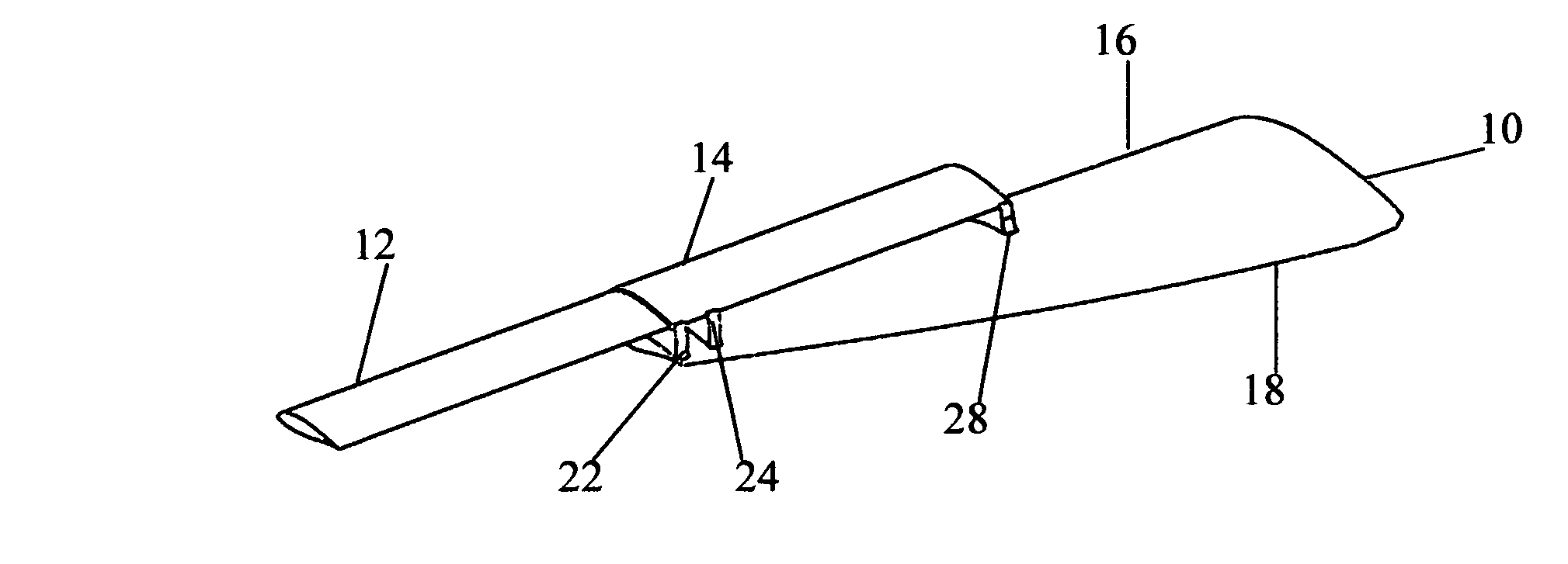
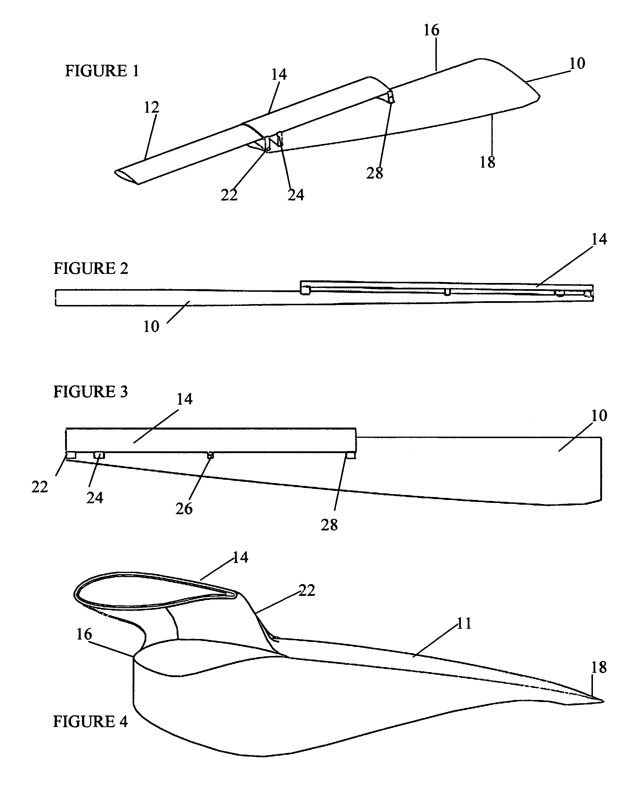
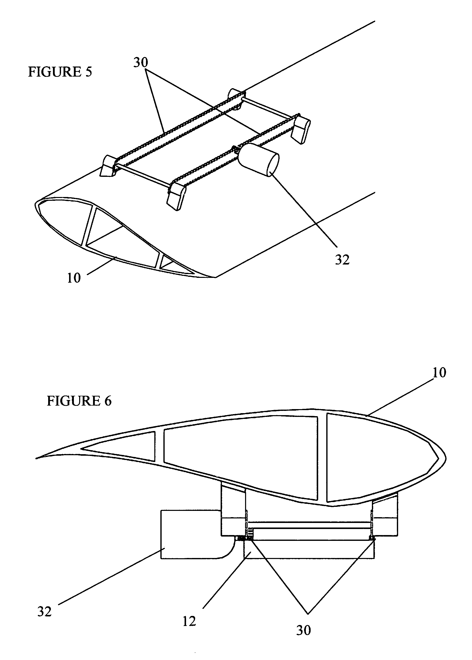
[0049]A wind power-generating device includes an electric generator housed in a turbine, which is mounted atop a tall tower structure anchored to the ground. The turbine is free to rotate in the horizontal plane such that it tends to remain in the path of prevailing wind current. The turbine has a rotor with variable pitch blades, which rotate in response to wind current. Each of the blades has a blade base section referred to as a root blade attached to a rotor hub and a blade extension referred to as an extender blade that is variable in length to provide a variable diameter rotor. The rotor diameter is controlled to fully extend the rotor at low flow velocity and to retract the rotor as flow velocity increases such that the loads delivered by or exerted upon the rotor do not exceed set limits. The power-generating device is held by the tower structure in the path of the wind current such that the power-generating device is held in place horizontally in alignment with the wind cur...


PUM


Abstract

A power generating system wherein a turbine is mounted on top of a tower or tethered underwater. The turbine includes a rotor having a main blade section connected to a rotor hub and an extender housing mounted on a top surface of the main blade section. The extender housing has an extender blade stored therein. An adjusting device positions the extender blade between a retracted position within the extender housing and an extended position to expose more or less of the rotor to the fluid flow. A generator is connected to the turbine for generating electrical energy.

Description

CROSS-REFERENCE TO RELATED APPLICATIONS[0001]This application is a Continuation of and claims priority under 35 U.S.C. § 119(e) to U.S. Provisional Patent Application No. 60 / 459,011 “Extendable Rotor Blades For Power Generating Wind And Ocean Current Turbines Within A Module Mounted Atop A Main Blade”, which was filed on Feb. 28, 2004 and which is incorporated herein by reference.BACKGROUND OF THE INVENTION[0002]1. Field of the Invention[0003]This invention relates to electric power-generating devices, such as wind turbines and ocean current turbines, and more particularly to an apparatus for extending and retracting extendable rotors of horizontal axis, axial flow wind or water turbines.[0004]2. Description of the Prior Art[0005]U.S. Pat. No. 3,606,571 of Wood entitled “Stowed Rotor” granted Sep. 20, 1971, describes a stowed rotor mounted atop the fuselage of an airplane. The rotor includes a rotatable housing unit mounted on a vertical shaft and provided with a pair of rotor blade...

Claims


Application Information

Patent Timeline
Patent Type & Authority Patents(United States)
IPC IPC(8): F02B63/04F03G7/08H02K7/18
CPCF03B17/061F03D1/0608F03D7/0224F05B2210/18Y02E10/725Y02E10/28Y02E10/721Y02E10/723F05B2240/2021Y02E10/72Y02E10/30Y02E10/20
Inventor DEHLSEN, JAMES G. P.
Owner UNITED TECH CORP
Why Eureka
Try Eureka