
Router using clock synchronizer for distributed traffic control

a technology of distributed traffic control and clock synchronization, applied in the field of routers using distributed processing, can solve the problems of increasing the workload of processors and memory for implementing fair queuing schedulers, the implementation of fair queuing schedulers is not practical for very large routers, and the difficulty of large-scale commercial services implemented by internet service providers. achieve the effect of raising the speed of the fair queuing algorithm

Inactive Publication Date: 2009-09-01
CHA YANG SOON
View PDF20 Cites 7 Cited by
  • Summary
  • Abstract
  • Description
  • Claims
  • Application Information

AI Technical Summary

Benefits of technology

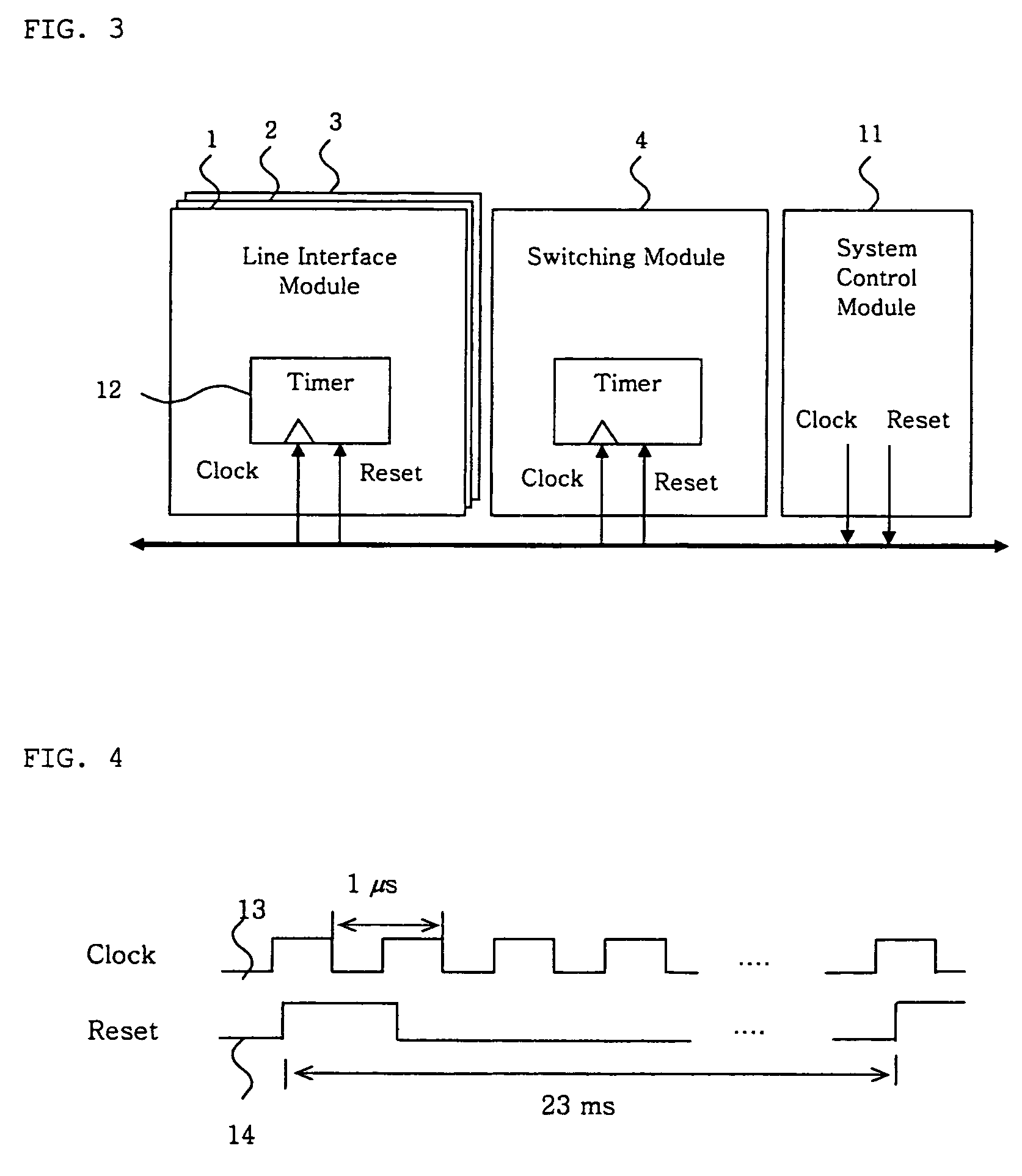
"The present invention provides a router architecture that performs fair queuing for real-time traffic control in packet switching networks. The architecture is designed for distributed processing of the fair queuing algorithm by many processors, which raises the speed of the algorithm in large scale routers economically. The time synchronization is achieved by the clock synchronizer providing the reference clock to the entire router system. The main object of this invention is the method of calculation of virtual finish time of each packet by use of separate processing element and the common reference clock in the routing system. The packet scheduler using this invention can guarantee QoS of the real-time traffic on a large scale."

Problems solved by technology

Real-time traffic QoS guarantee in the packet switching network is achieved on a small scale at the experimental level, but large scale implementation for commercial services by the internet service provider is still in difficulties.
Increasing speed of links and increasing number of ports cause problems in that demands on computing resources such as processor and memory for implementing fair queuing scheduler get larger.
There are opinions that implementation of fair queuing schedulers is not practical for very large router.
Secondly, it is increasing the processing speed of the hardware.
These two methods have limitation and we are in doubt about the economy of the solutions.

Method used


Image

  • Router using clock synchronizer for distributed traffic control
  • Router using clock synchronizer for distributed traffic control
  • Router using clock synchronizer for distributed traffic control

Examples


Embodiment Construction

[0014]Hereinafter, a preferred embodiment of the present invention will be described with reference to the accompanying drawings. In the following description and drawings, the same reference numerals are used to designate the same or similar components, and so repetition of the description on the same or similar components will be omitted.

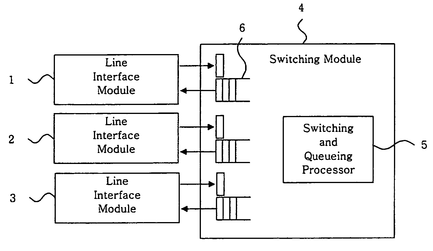
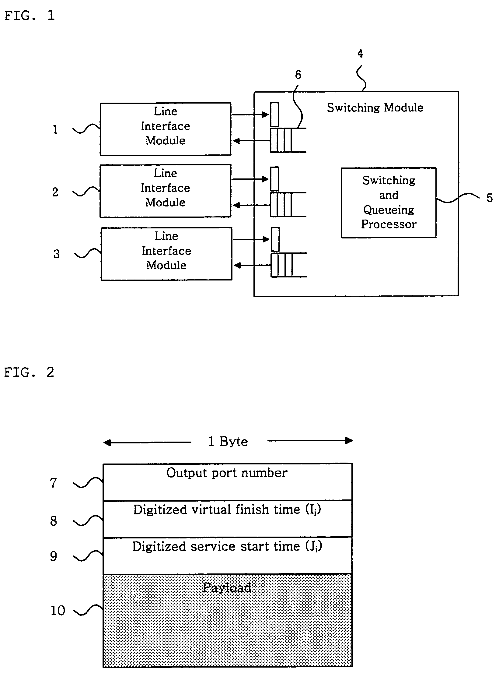
[0015]Referring to FIG. 1, a router according to one embodiment of this invention comprises a plurality of line interface modules 1, 2, and 3 connected to a switching module 4. The usual number of line interface modules which can be installed to the router is 16 and a large scale router system can have more than 32 line interface modules. Each line interface module is connected to a communication link. Packets arriving through the communication link are sent to the switching module 4. The switching and queuing processor 5 in the switching module 4 forwards the packets to the destination line interface module so that the packets are transmitted to ...


PUM


Abstract

A router using distributed processing for FIB look-up and fair queuing algorithm is invented. The real-time traffic includes voice and video and should be transmitted in a certain time limit. Otherwise, the quality of the traffic is affected and the information is no longer useful. Packet scheduler in the router transmits packets within the time limit. However, the packet scheduler is not fast enough compared to the link speed and the size of the router. This invention uses a plurality of processors and almost identical time for each processor. FIB look-up and switching are performed by different processors to reduce the processing time. The traffic control algorithm can be performed independently by each processor. Thus, the processing speed of the entire router can be raised.

Description

BACKGROUND OF THE INVENTION[0001]1. Field of the Invention[0002]The present invention relates to a router using distributed processing, and more particularly to a router using distributed processing of FIB (Forwarding Information Base) look-up and / or real-time traffic control algorithms in the packet switching network such as the Internet.[0003]2. Description of the Prior Art[0004]As generally known in the art, the main motivation is to provide telecommunication services to the internet users. For this, the FIB look-up is performed by the processor or processing elements on the line interface modules to make the processing faster. A fair queuing algorithm is used to avoid congestion in the routers. Fair queuing is a packet scheduling algorithm based on the calculation of virtual finish time of each packet and sorting the packets in the increasing order of the virtual finish time. The packets are transmitted in that order. By doing this, the packets are transmitted within the virtual...

Claims


Application Information

Patent Timeline
Patent Type & Authority Patents(United States)
IPC IPC(8): H04L12/28H04J3/06H04L12/56
CPCH04L45/60H04J3/0685A47G19/22A47G19/2255A47G2019/2277
Inventor KIM, KICHEON
Owner CHA YANG SOON
Learn More