Endoscopic clip applying apparatus with improved aperture for clip release and related method

a technology of applicator and clip, which is applied in the field of applicator of surgical clips, can solve the problems of limited space and visibility, time-consuming and difficult to perform complex manipulations, and certain inadequacies in the available surgical equipment, and achieve the effect of increasing the width of the jaw apertur

Active Publication Date: 2009-09-08
TELEFLEX MEDICAL INC
View PDF29 Cites 134 Cited by
  • Summary
  • Abstract
  • Description
  • Claims
  • Application Information

AI Technical Summary

Benefits of technology

[0013]According to one embodiment, an apparatus for applying surgical clips comprises a jaw assembly and a jaw opening member. The jaw assembly comprises first and second opposing jaw members defining a jaw aperture therebetween for receiving a clip. The first and second jaw members are pivotable for varying a width of the jaw aperture. The jaw opening member comprises a distal portion generally adjacent to the first and second jaw members. The distal portion is movable into engagement with the first and second jaw members for increasing the width of the jaw aperture.
[0016]According to still another embodiment, an apparatus for applying surgical clips comprises a jaw assembly, a feeding device, and a jaw opening member. The jaw assembly comprises first and second opposing jaw members defining a jaw aperture therebetween for receiving a clip. The first and second jaw members are pivotable for varying a width of the jaw aperture. The feeding device is axially movable toward the jaw aperture for feeding a clip therein. The jaw opening member is engagable with the feeding device for movement therewith, and is movable into engagement with the first and second jaw members for increasing the width of the jaw aperture.
[0017]In addition, a method is disclosed herein for improving the release of a clip from a clip applying apparatus. A jaw assembly of the clip applying apparatus is opened to increase a width of a jaw aperture defined between first and second opposing jaw members of the jaw assembly. A biasing force is imparted to the first and second jaw members to further increase the width of the jaw aperture, whereby the further increased width facilitates releasing the clip disposed in the jaw aperture from the clip applying apparatus.
[0018]It is therefore an object of the subject matter disclosed herein to provide an endoscopic clip applier with improved aperture for clip release and a method for increasing the jaw aperture so as to improve clip release.

Problems solved by technology

Performing vessel ligation using surgical thread requires complex manipulations of the needle and suture material to form the knots required to secure the vessel.
Such complex manipulations are time-consuming and difficult to perform, particularly in endoscopic surgical procedures, which are characterized by limited space and visibility.
As endoscopic techniques have been developed, certain inadequacies in the available surgical equipment have become apparent.
For example, the jaws of the applier, which are typically used to close a clip around a vessel, may exert unequal pressure on the clip, resulting in a “scissoring” effect and damage to the vessel.
In other instances, the clip may not be properly oriented when it is placed within the jaws or may slip out of alignment during application.
This may result in the loss or misapplication of the clip.
In still other instances, the applier may jam or may simply fail to deploy a clip.
Furthermore, existing multiple clip applier systems have been designed for symmetric clips and are not well suited to satisfy design issues unique to asymmetric clips.
By contrast, asymmetric clips cannot easily be retained in opposing channels because the clip's legs deform when the clip is closed.
Thus, conventional clip advancing mechanisms designed for symmetric clips may not reliably advance asymmetric clips.
In addition, conventional clip advancing mechanisms designed for symmetric clips may not provide the ability to approximate a clip.
Therefore, conventional clip appliers designed for symmetric, metal clips suffer from certain deficiencies and are not adapted to deliver asymmetric, polymer based clips.
In the use of such clip appliers, it has been found that difficulties may sometimes arise when attempting to release an applied clip from the jaws of the clip applier.
Specifically, in some instances, clips may tend to become caught or hung up in the jaws in a manner that impedes their easy release therefrom.

Method used


Image

  • Endoscopic clip applying apparatus with improved aperture for clip release and related method
  • Endoscopic clip applying apparatus with improved aperture for clip release and related method
  • Endoscopic clip applying apparatus with improved aperture for clip release and related method

Examples


Embodiment Construction

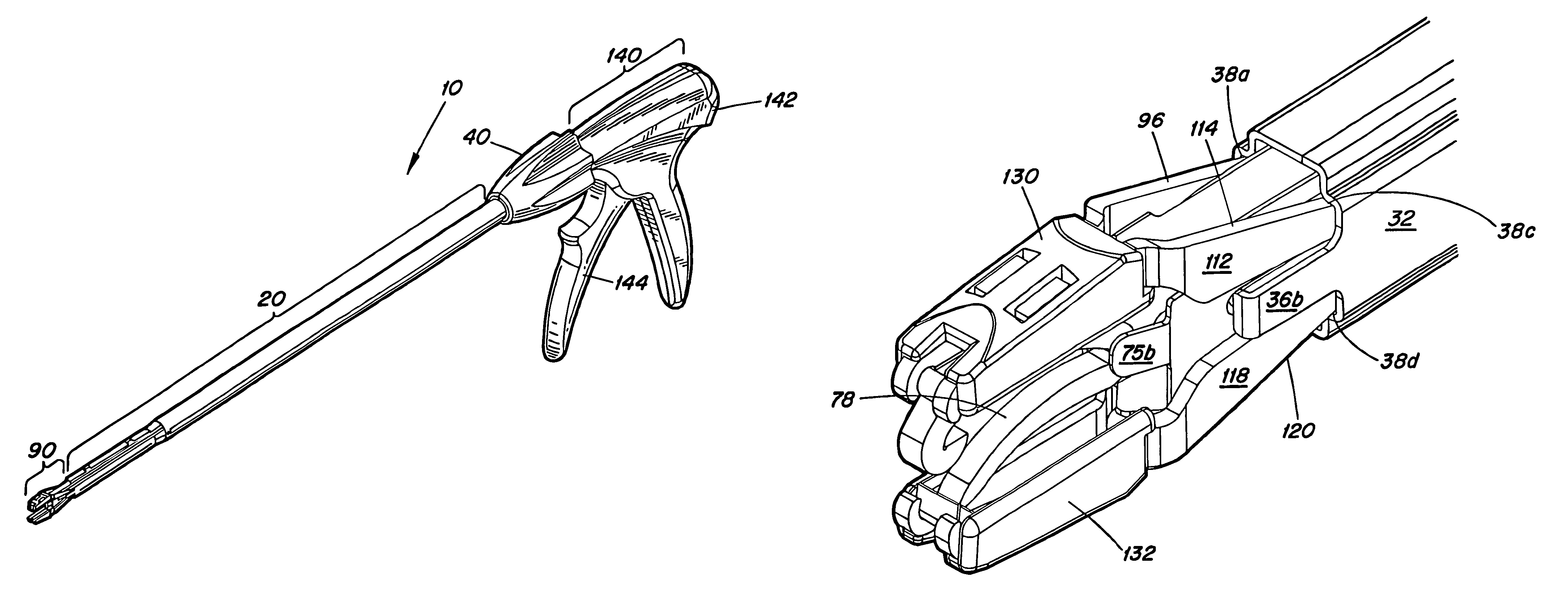
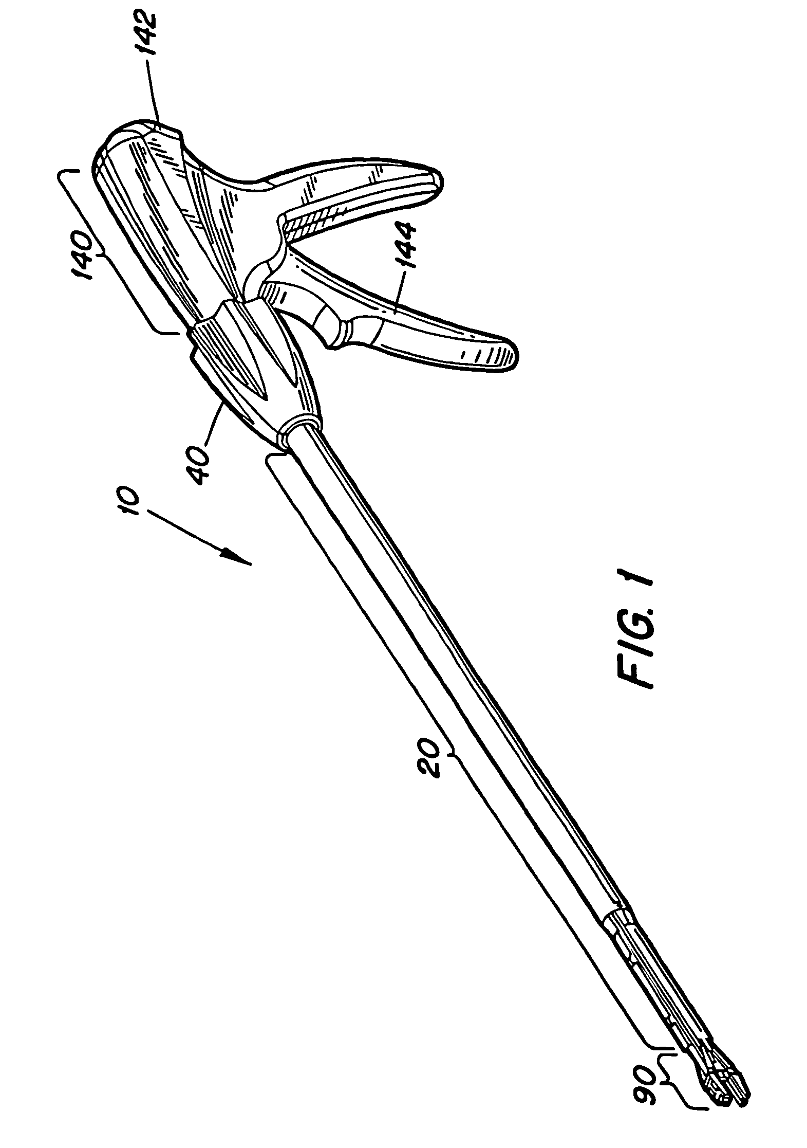
[0057]Referring to FIG. 1, an exemplary embodiment of an endoscopic clip applier 10 in accordance with the subject matter disclosed herein includes an elongate or shaft assembly generally designated 20, a jaw assembly generally designated 90 disposed at a distal end thereof, and a handle assembly generally designated 140 disposed at a proximal end thereof. Handle assembly 140 includes a stationary grip 142 and a movable trigger 144 for actuating clip applier 10. In use, jaw assembly 90 may be positioned inside a body cavity, for example by passing shaft assembly 20 through an endoscopic cannula, to apply a ligating clip to a body vessel.

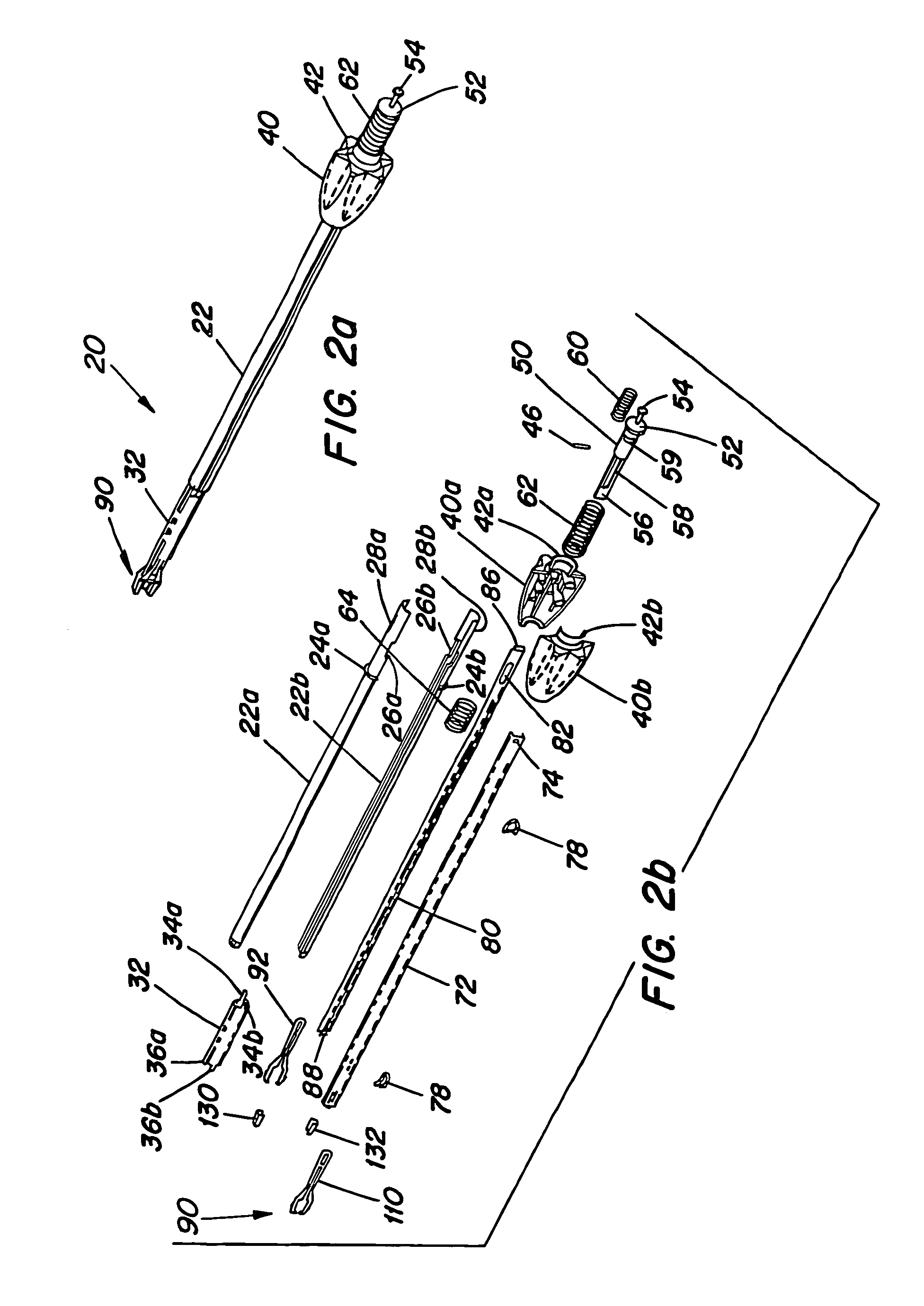
[0058]FIG. 2A is a perspective view and FIGS. 2B and 2C are exploded assembly views of an exemplary embodiment of shaft assembly 20 and jaw assembly 90. Shaft assembly 20 includes an elongate member such as a cylindrical outer shaft member 22, which may be formed from two semi-cylindrical outer shaft members 22A and 22B, respectively. It will be appr...


PUM


Abstract

An apparatus for applying surgical clips includes a jaw assembly and a jaw opening member. The jaw assembly includes first and second opposing pivotable jaw members that define a variable-width jaw aperture therebetween for receiving a clip. The jaw opening member is movable into engagement with the first and second jaw members for increasing the width of the jaw aperture, thereby improving the release of a clip from the jaw assembly.

Description

TECHNICAL FIELD[0001]The subject matter disclosed herein generally relates to an applier for surgical clips. More particularly, the subject matter disclosed herein relates to an endoscopic ligating clip applier capable of sequentially delivering a number of clips in a clip channel.BACKGROUND ART[0002]Laparoscopic, endoscopic, and other minimally invasive surgical techniques enable surgeons to perform fairly complicated procedures through relatively small entry points in the body. The term “laparoscopic” refers to surgical procedures performed on the interior of the abdomen, while the term “endoscopic” refers more generally to procedures performed in any portion of the body. Endoscopic surgery involves the use of an endoscope, which is an instrument permitting the visual inspection and magnification of a body cavity. The endoscope is inserted into a body cavity through a cannula extending through a hole in the soft tissue protecting the body cavity. The hole is made with a trocar, wh...

Claims


Application Information

Patent Timeline
Patent Type & Authority Patents(United States)
IPC IPC(8): A61B17/10A61B17/28
CPCA61B17/10A61B17/1285A61B2017/2926
Inventor HUGHETT, J. DAVID
Owner TELEFLEX MEDICAL INC
Why Eureka
Try Eureka