Optical pickup device

a pickup device and optical technology, applied in the field of optical pickup devices, can solve the problems of increasing the burden of adjusting work, difficult to adopt the above-mentioned three-beam type, and difficult to achieve the above-mentioned adjustment type, so as to reduce the size of the photo detector and efficiently dispose of the photo detector

Inactive Publication Date: 2009-09-08
FUNAI ELECTRIC CO LTD
View PDF7 Cites 2 Cited by
  • Summary
  • Abstract
  • Description
  • Claims
  • Application Information

AI Technical Summary

Benefits of technology

[0012]An object of the present invention is to provide an optical pickup device including light sources of three wavelengths, a hologram for generating a servo control signal and a photo detector, which can reduce an area of light receiving portion (detector) of the photo detector. Another object of the present invention is to realize a small size of the photo detector by reducing the area of light receiving portion of the photo detector.
[0014]According to this structure, concerning 1st order diffracted light of longest wavelength light that inherently forms a spot on an outer most part of the light receiving portion because it has a largest diffraction angle by the hologram element due to the longest wavelength or 1st order diffracted light of shortest wavelength light that inherently forms a spot on an inner most part of the light receiving portion because it has a smallest diffraction angle by the hologram element due to the shortest wavelength, it is possible to make a spot position in either the light receiving portions for receiving the +1st order light or the light receiving portion for receiving the −1st order light close to a position of a spot formed by light of medium wavelength or to form the spot between two other wavelength spots. In this case, concerning the other light receiving portion, the spot position is distant from the two other wavelength spots and is formed on further outer or inner side. However, since its distance increases, it is possible to separate the light receiving portion where the spot is formed from the light receiving portion for two other wavelengths. In other words, for the former case it is possible to reduce an area of the light receiving portion, and in the latter case the area of the light receiving portion is scarcely increased. For this reason, a total area of the light receiving portion disposed on the photo detector can be reduced, so that a cost of the photo detector can be reduced.
[0016]According to this structure, since the two-wavelength composite light source is used, the whole structure of the optical pickup device can be realized in a small size. In addition, since the two-wavelength composite light source is a structure in which light emission points of different wavelength light are arranged at a constant interval, a desired light source arrangement can be realized only by adjusting an attachment angle of the two-wavelength composite light source, so that a burden of an adjustment work can be reduced.
[0018]According to this structure, in either the light receiving portion for receiving the +1st order light or the light receiving portion for receiving the −1st order light, spots of the 1st order diffracted light of the light emitted from the three light sources can be condensed substantially at one point. Concerning the other light receiving portion, since the spot positions of the 1st order diffracted light of the light emitted from the three light sources are distant from each other largely, it is possible to divide the light receiving portion into parts where the spot are formed separately. In other word, for the former case it is possible to reduce an area of the light receiving portion largely, and in the latter case the area of the light receiving portion is scarcely increased. For this reason, a total area of the light receiving portion disposed on the photo detector can be reduced, so that a cost of the photo detector can be reduced.
[0020]According to this structure, the entire structure of the optical pickup device can be downsized by using the two-wavelength composite light source. In addition, since the two-wavelength composite light source is a structure in which light emission points of different wavelength light are arranged at a constant interval, a desired light source arrangement can be realized only by adjusting an attachment angle of the two-wavelength composite light source, so that a burden of an adjustment work can be reduced.
[0022]According to this structure, the optoelectronic integrated circuit (OEIC) to be disposed on the photo detector can be disposed on the photo detector efficiently, so a size of the photo detector can be reduced.

Problems solved by technology

Therefore, supposing that one optical pickup device is capable of emitting light beams having three wavelengths for a CD, a DVD and a BD, usage of this three-beam type may increase a burden of the adjusting work.
In addition, the above-mentioned adjustment will be difficult particularly for a BD because it is necessary to minimize a beam spot condensed onto the recording surface of the medium formed by the light beam emitted from the light source.
For this reason, it is not easy to adopt the above-mentioned three-beam type for the optical pickup device having three light sources of three wavelengths for a CD, a DVD and a BD.
For this reason, an area of the light receiving portion 112 of the photo detector 111 should be enlarged, which causes an increase of cost for manufacturing the photo detector 111 and an increase of size of the photo detector 111.

Method used


Image

  • Optical pickup device
  • Optical pickup device
  • Optical pickup device

Examples


first embodiment

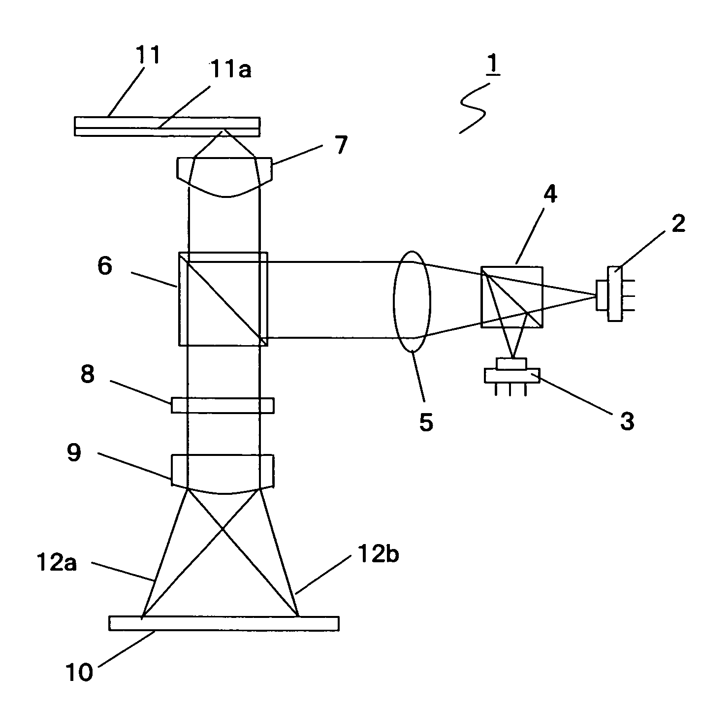
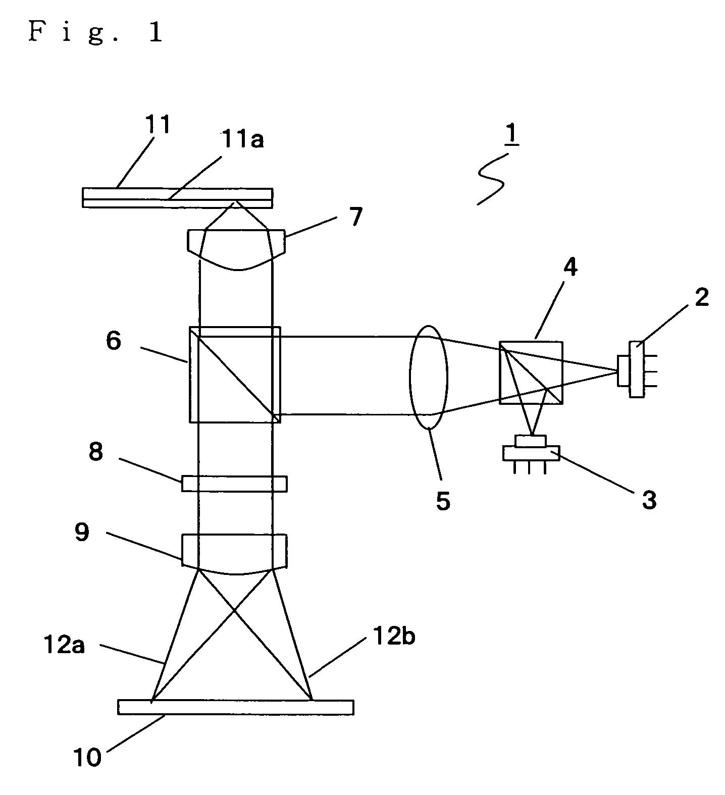
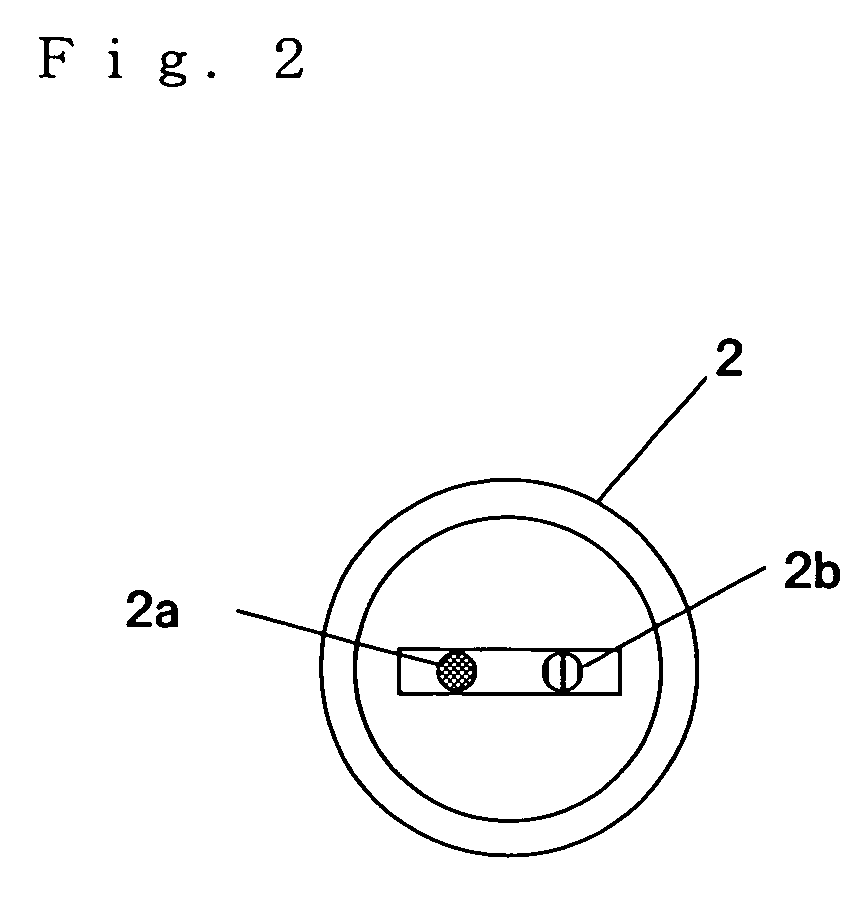
[0036]The two-wavelength composite light source 2 is made up of a monolithic semiconductor laser having two light emission points that can emit a laser beam of 780 nm band supporting a CD and a laser beam of 650 nm band supporting a DVD. In addition, the light source 3 is a semiconductor laser that can emit a single wavelength laser beam of 405 nm band supporting a BD. Although the monolithic semiconductor laser is used as the two-wavelength composite light source 2 in the first embodiment, the present invention is not limited to this structure. For example, it is possible to use a hybrid semiconductor laser may be used, in which light sources manufactured separately are housed in one package.

[0037]The dichroic prism 4 allows the laser beams from the two-wavelength composite light source 2 that emits laser beams for a CD and a DVD to pass through, while it reflects the laser beam from the light source 3 that emits a laser beam for a BD. The laser beam that is allowed to pass through...

second embodiment

[0059]Note that FIG. 7 is an explanatory diagram for explaining a relationship between positions of the beam spots formed on the photo detector 10 by the 0 order light of the laser beams that are emitted from the two-wavelength composite light source 2 and the light source 3 and pass the hologram element 8 in the

[0060]An action when the two-wavelength composite light source 2 and the light source 3 are arranged as described above will be described. FIG. 8 is a schematic diagram showing schematically that the +1st diffracted light 12a and the −1st order light 12b generated by diffraction of the laser beams for a CD, for a DVD and for a BD in the hologram element 8 are received by the light receiving portions 14 and 15 provided to the photo detector 10 of the optical pickup device 1 in this embodiment.

[0061]As shown in FIG. 8, positions 17a, 17b and 17c of the spots formed on the light receiving portion 15 by the −1st order light 12b of the laser beams for a CD, for a DVD and for a BD...


PUM

PropertyMeasurementUnit
wavelengthaaaaaaaaaa

Abstract

An optical pickup device includes a two-wavelength composite light source that can emit laser beams for a CD and for a DVD, a light source that can emit a laser beam for a BD, a hologram element and a photo detector. When spots formed on the photo detector by 0 order light generated by diffraction of the three laser beams in the hologram element are first, second and third spots in the descending order of the wavelength of the laser beams, an attachment angle of the two-wavelength composite light source is adjusted so that positions of the third spot and the second spot match substantially each other while a position of the first spot is shifted from the position of the second spot in the same direction as a diffraction direction of +1st diffracted light.

Description

[0001]This application is based on Japanese Patent Application No. 2005-328656 filed on Nov. 14, 2005, the contents of which are hereby incorporated by reference.BACKGROUND OF THE INVENTION[0002]1. Field of the Invention[0003]The present invention relates to an optical pickup device that is capable of recording information on an optical recording medium or reading out information recorded on an optical recording medium using a light source emitting light toward a recording layer of the optical recording medium. In particular, the present invention relates to a structure of the optical pickup device that support three wavelengths and can downsize a light receiving portion of a photo detector and the photo detector itself.[0004]2. Description of Related Art[0005]There are many types of the optical recording media including a compact disk (hereinafter referred to as a CD), a digital versatile disk (hereinafter referred to as a DVD), a Blu-Ray Disk (hereinafter referred to as a BD) that...

Claims


Application Information

Patent Timeline
Patent Type & Authority Patents(United States)
IPC IPC(8): G11B7/00
CPCG11B7/1275G11B7/1353G11B7/13G11B7/0903G11B2007/0006
Inventor NAGASHIMA, KENJI
Owner FUNAI ELECTRIC CO LTD
Why Eureka
Try Eureka