
In-mold label system plastic container

a label system and plastic container technology, applied in the field of in-mold labeled plastic containers, can solve the problems of inability to eliminate and invite a drop in yield, and achieve the effect of high accuracy and free, and excelling in aesthetic design

Inactive Publication Date: 2009-09-15
DAI NIPPON PRINTING CO LTD
View PDF45 Cites 2 Cited by
  • Summary
  • Abstract
  • Description
  • Claims
  • Application Information

AI Technical Summary

Benefits of technology

[0006]Such problems can be solved to some extent by eliminating dimensional fluctuations of the inmold label and fix to the inside of the female mold by some devices or other, but it is all but impossible to eliminate errors in every dimension of inmold labels which are mass-produced, and the installation of a label fixing device inside the female mold would complicate the fitting of the label in itself and invite a drop in yield, which is undesirable.
[0029]According to this invention, the pressure of the molten resin is sufficiently transmitted to the flange part to provide an inmold labeled type plastic container which is highly accurate and free from unintended unlabeling or wrinkling, and excels in aesthetic design.

Problems solved by technology

However, where such an in mold labeling system was used, there arose a problem that the inmold label fitted within the female mold was shoved by molten resin, when it was extruded, to give rise to wrinkles or molten resin flowed into the gap between the female mold and the inmold label.
Such problems can be solved to some extent by eliminating dimensional fluctuations of the inmold label and fix to the inside of the female mold by some devices or other, but it is all but impossible to eliminate errors in every dimension of inmold labels which are mass-produced, and the installation of a label fixing device inside the female mold would complicate the fitting of the label in itself and invite a drop in yield, which is undesirable.

Method used


Image

  • In-mold label system plastic container
  • In-mold label system plastic container
  • In-mold label system plastic container

Examples


example 1

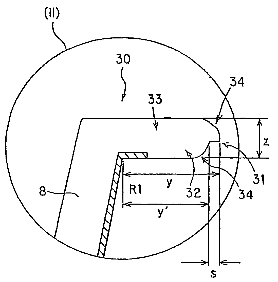
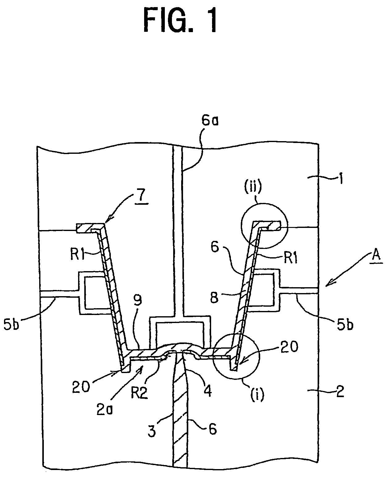
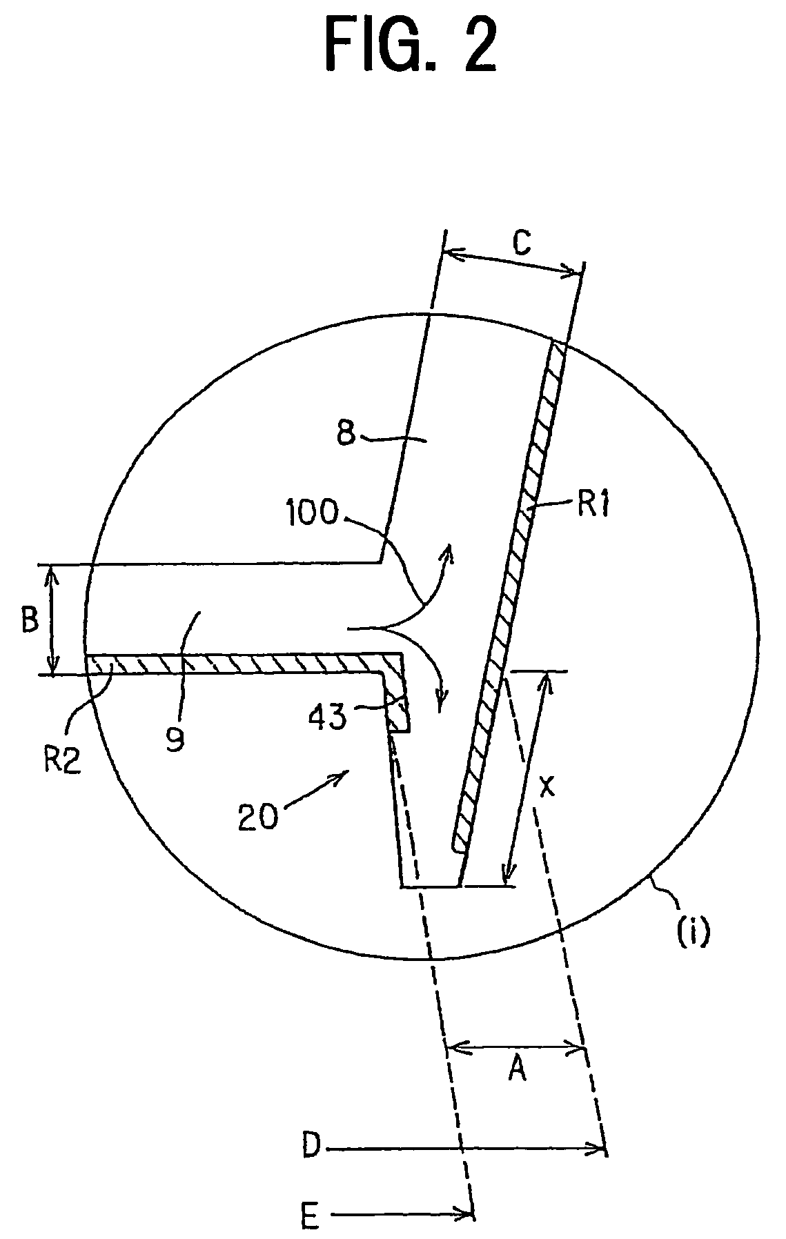
[0098]As the resin for the plastic container body, HDPE (M.F.R.: 40 g / 10 min) was used (resin temperature: 220° C.); this resin and a label of 90 μm in thickness were integrally molded by the molding method for inmold labeled type plastic containers illustrated in FIG. 1 to fabricate an inmold labeled type plastic container of Embodiment 1, and it was filled with a content.

[0099]Details of the parts of the inmold labeled type plastic container of this Embodiment 1 including the dimensions are as follows:

[0100]Dimension of the bottom rim: 0.9 mm

[0101]Thickness of the intersection between the bottom rim and the container's bottom part: 1.0 mm

[0102]Thickness of the container's bottom part: 1.1 mm

[0103]Thickness of the container's side part: 0.77 mm

[0104]Flange width: 4.0 mm

[0105]Flange thickness: 1.0 mm

[0106]Relationship between the fluid length (L) of the injected molten resin and the average wall thickness (t) of the container (L / t): About 175

[0107]Configuration of the label: oriente...

example 2

[0115]As the injected resin material for the plastic container body, polypropylene was used and, as the label material a film formed by stacking three layers of polyethylene terephthalate film (12 μm) / aluminum foil (15 μm) / polypropylene film (60 μm) was used. This label material, after characters and pictures were printed on the PET film as the thin layer positioned on its front (outermost) side and the aluminum foil as the barrier layer was laminated by using an adhesive, was formed into a three-layered film with the polypropylene film as the thin layer positioned on its rear (innermost) side being laminated by using an adhesive, and punched into prescribed shapes (a fan shape for the side label and a round having a gate hole at the center for the bottom label).

[0116]Then, as shown in FIG. 1, these labels (the side label R1 and the bottom label R2) were arranged on the side face and the bottom face of the female mold 2 and, after the male mold 1 was pressed in from above, the resin...

example 3

[0129]A face of a biaxially oriented polypropylene film of 30 □m in thickness was coated with a polyurethane adhesive to a thickness of 4 g / m2 (in a dry state) to form an adhesive layer, and a biaxially oriented polyethylene terephthalate film of 12 μm in thickness, on one face of which a prescribed print pattern was printed to form a printed layer was dry-laminated over a face of the adhesive layer. Next, a face of this biaxially oriented polyethylene terephthalate film was coated with a polyurethane adhesive to a thickness of 4 g / m2 (in a dry state) in the same way as above to form an adhesive layer, and further a biaxially oriented polyethylene terephthalate film on which silicon oxide of 12 μm in thickness was vapor-deposited was dry-laminated on a face of the adhesive layer. After that, the face of the biaxially oriented polyethylene terephthalate film on which silicon oxide was vapor-deposited was coated with a polyurethane adhesive to a thickness of 4 g / m2 (in a dry state) in...


PUM

PropertyMeasurementUnit
thicknessaaaaaaaaaa
widthaaaaaaaaaa
widthaaaaaaaaaa

Abstract

The main object is to provide an inmold labeled type plastic container which can be fabricated, even if there are some dimensional errors in the inmold label, with no damage to aesthetic design or no drop in yield is to be provided, and further an inmold labeled type plastic container which allows the consumer to drink or eat the content safely even if he or she brings his or her mouth into direct touch with the opening is to be provided. A bottom rim is disposed in the lower part of the inmold labeled type plastic container, with its dimension being not less than 0.3 mm but not more than 20 mm, and the inmold labeled type plastic container to be provided is labeled on its bottom rim in a similar way to the side part of the container.

Description

TECHNICAL FIELD[0001]The present invention relates to an inmold labeled type plastic container.BACKGROUND ART[0002]There are a variety of methods of labeling a side part of a plastic container including one by which the rear face of a label is glued and the label is stuck to the plastic container and another by which a seal type label to whose rear face an adhesive is already applied is stuck.[0003]Among others, the inmold labeling system by which a label is inserted at the same time as molding of a plastic container to form the container and the label integrally has come to be frequently used in recent years. Since a plastic container formed by this inmold labeling system uses neither glue nor adhesive and accordingly its label and resin are melt-joined, the label does not come off even in a state of high temperature and high humidity. Therefore, such plastic containers are in very high demand for use in humid places such as bathrooms and toilets and as containers whose contents ar...

Claims


Application Information

Patent Timeline
Patent Type & Authority Patents(United States)
IPC IPC(8): B65D6/02B65D1/42B29C45/00B29C45/14B65D1/40B65D5/20
CPCB29C45/0046B29C45/14778B65D1/40B65D5/209B29C45/14467B29C2045/14918B65D2203/02B29L2031/7132B29C2045/14967B29C45/14B65D1/00B65D1/26G09F3/08
Inventor SHINOGI, NORIKAZU
Owner DAI NIPPON PRINTING CO LTD
Learn More