Method of determining and/or evaluating a differential optical signal

a technology of differential optical signal and determining method, which is applied in the direction of optical detection, optical radiation measurement, instruments, etc., can solve the problem of inability to reliably evaluate the incoming signal, and achieve the effect of any loss of sensitivity

Active Publication Date: 2009-09-15
ELMOS SEMICON SE
View PDF8 Cites 8 Cited by
  • Summary
  • Abstract
  • Description
  • Claims
  • Application Information

AI Technical Summary

Benefits of technology

[0024]Taking this prior art as a starting point, the object of the present invention is to implement this method in a simplified digital form as far as possible without any loss of sensitivity.

Problems solved by technology

It is therefore impossible to reliably evaluate the incoming signal when the ambient light conditions are subject to considerable fluctuations.

Method used


Image

  • Method of determining and/or evaluating a differential optical signal
  • Method of determining and/or evaluating a differential optical signal
  • Method of determining and/or evaluating a differential optical signal

Examples


Embodiment Construction

[0034]The invention is now described in detail by way of example with reference to the accompanying drawings. However the embodiments are only examples, which are not intended to limit the inventive concept to a specific arrangement.

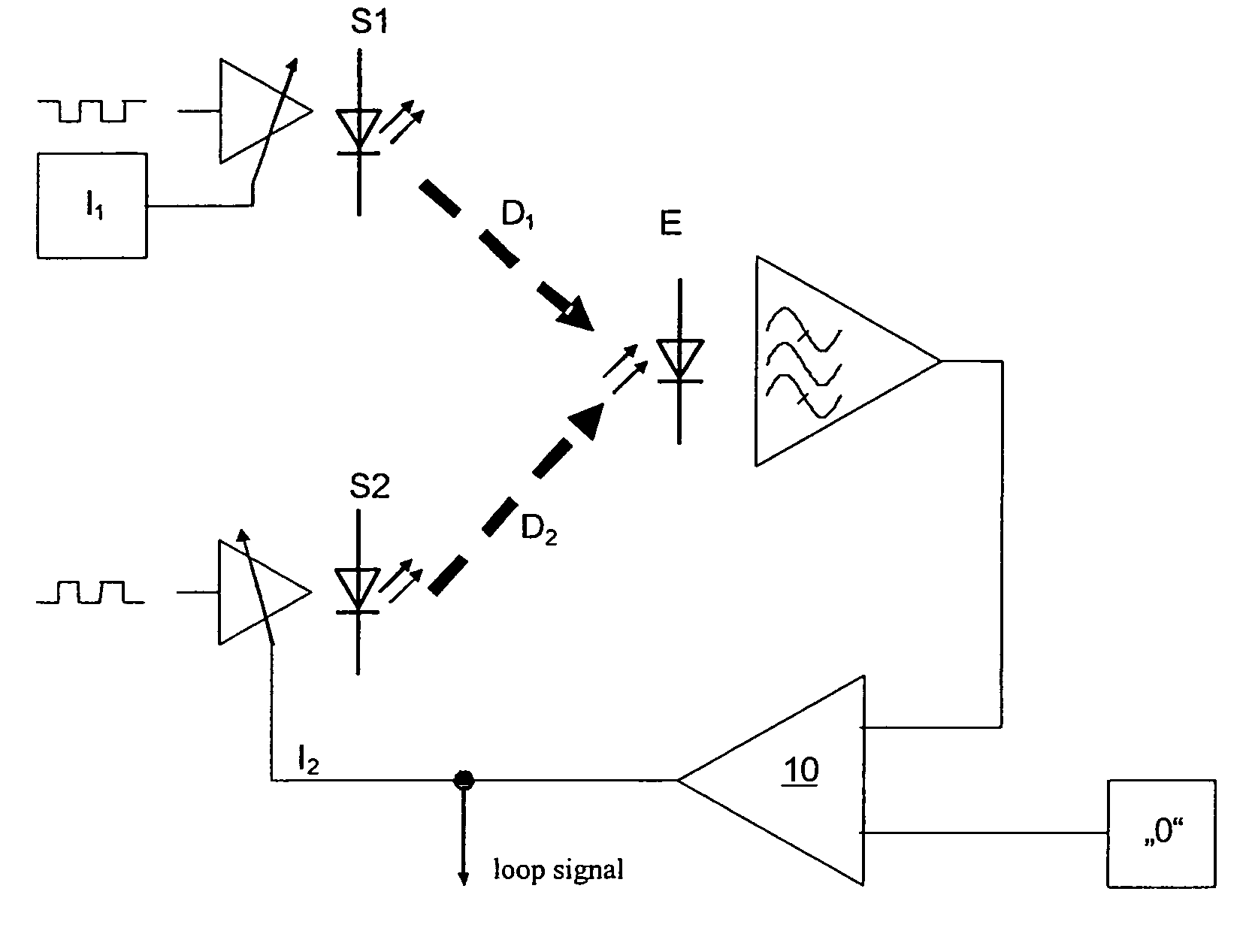
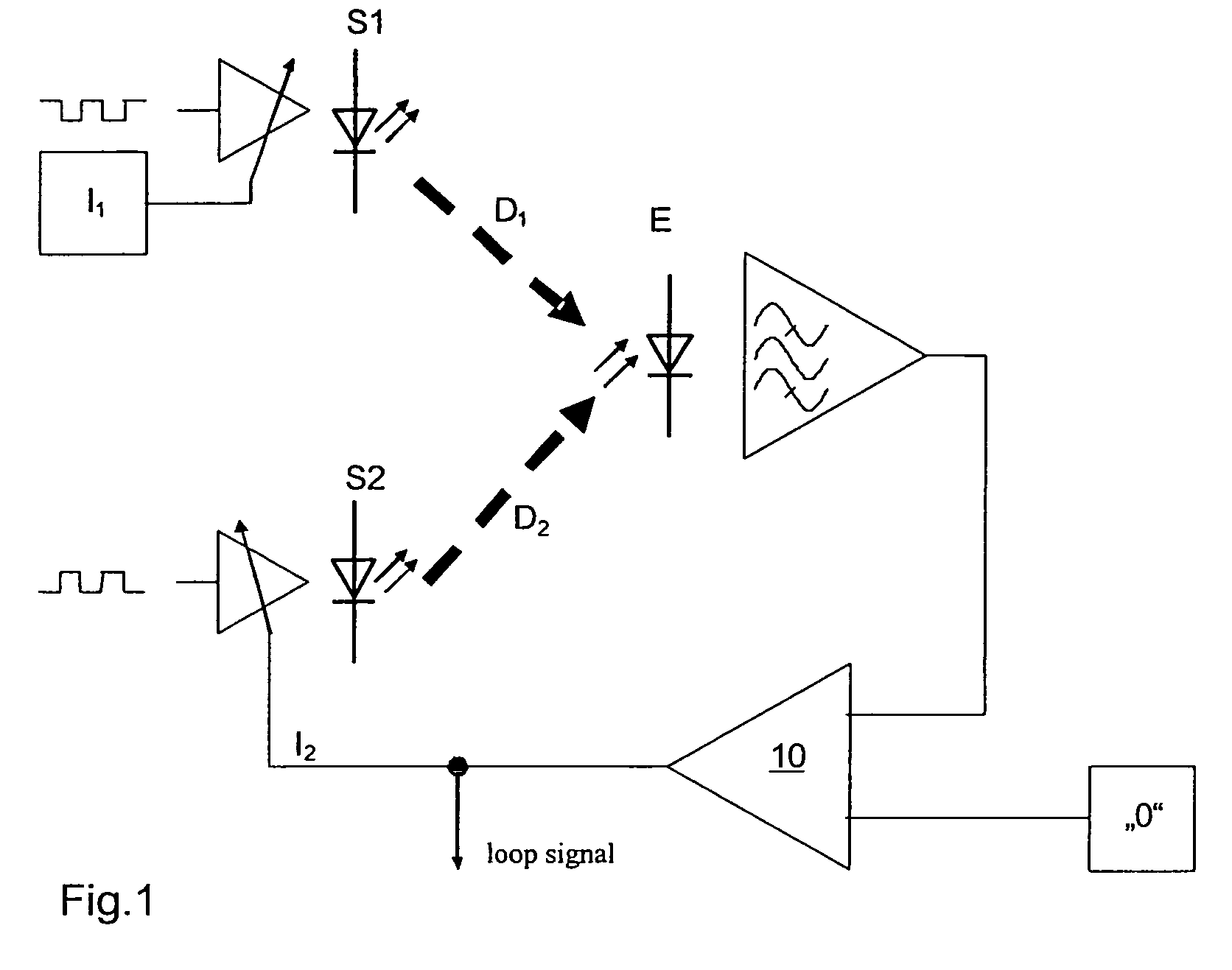
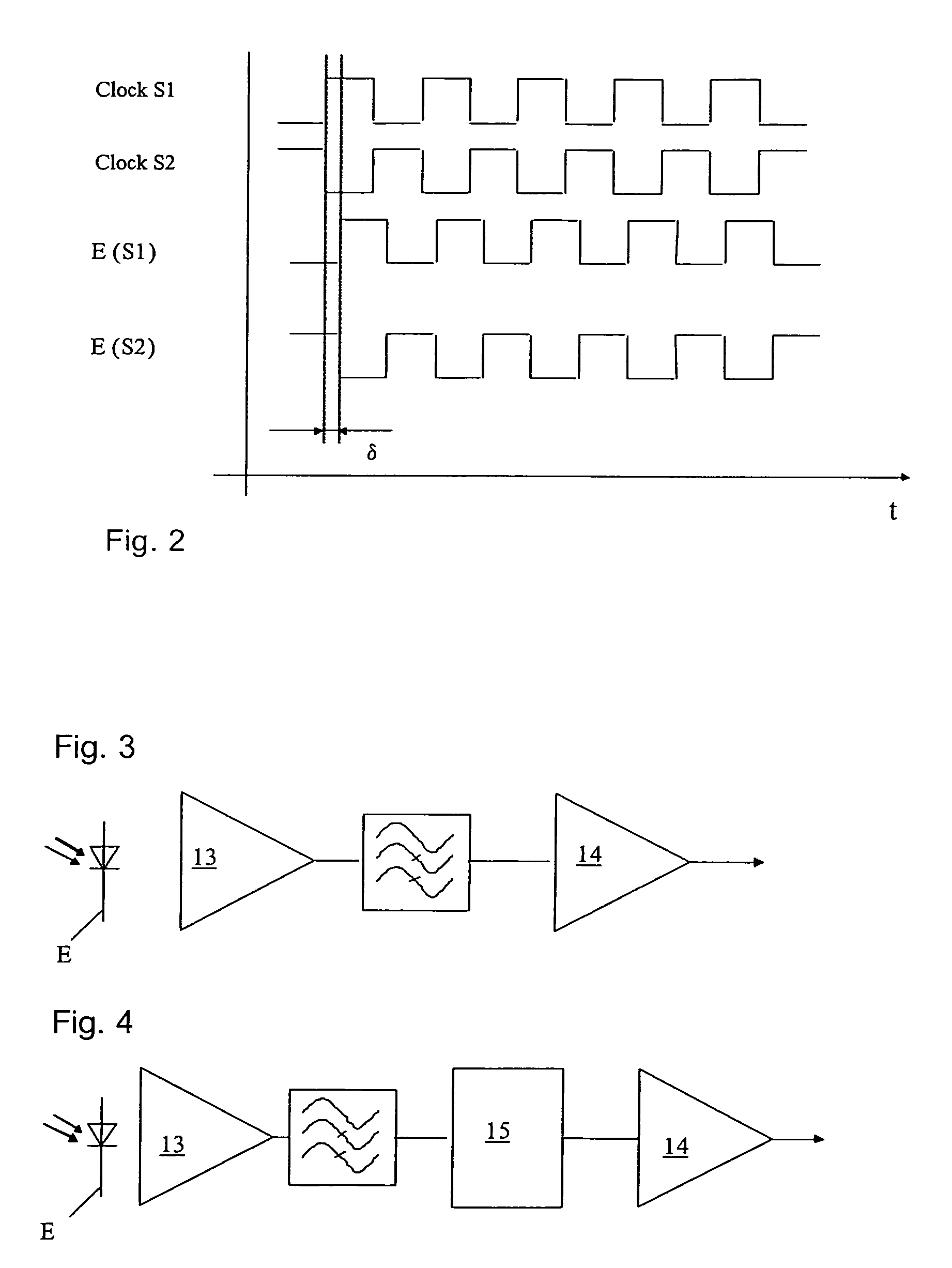
[0035]The figures show a method for determining and / or evaluating a differential optical signal with at least two first light sources S1, S2 which emit light in a sequentially phased manner. At least one receiver E is provided to receive the signal thus emitted, this receiver receiving a sequentially emitted alternating light component from the first light sources S1, S2. The light intensity which is irradiated in the measuring arrangement through at least one light source S1, S2, which may also be a compensation light source K, is then regulated such that the clock-synchronous alternating light component, which occurs between the different phases, becomes zero at the receiver E. This was illustrated in detail at the outset in the introductory part of th...


PUM


Abstract

The invention relates to a method for determining and / or evaluating a differential, optical signal. According to the invention, at least two first light sources (S1, S2) which are sequentially clocked in terms of light and emitted in a phased manner are provided, in addition to at least one receiver (E) which is used to receive at least the alternating light portion arising from the first light sources (S1, S2). The light intensity radiating through at least one light source (S1, S2) in the measuring arrangement is controlled in such a manner that the clock synchronous alternating light portion, which occurs between different phases, is zero in the receiver (E). By determining the reception signal in the receiver (E) in relation to the phase position in order to regulate the radiated light intensity and by producing an adjustable variable (R) directly or by adding current in the receiver, it is possible to simplify digital implementation of the method with as little sensitivity loss as possible.

Description

REFERENCE TO RELATED APPLICATIONS[0001]The present application claims the priority of the German patent application 103 46 741.6, filed on Aug. 10, 2003, the disclosed content of which is hereby explicitly also made the subject matter of the present application.FIELD OF THE INVENTION[0002]The invention relates to a method for determining and / or evaluating a differential optical signal according to the preamble of Claim 1 or Claim 4.PRIOR ART[0003]Photodiodes have a sensitivity to modulated light which is dependent on the absolute brightness, the so-called “ambient light effect”. The incoming signal of a retroreflective sensor therefore depends not just on the reflection ratio which is to be measured, but also on the ambient light. It is therefore impossible to reliably evaluate the incoming signal when the ambient light conditions are subject to considerable fluctuations.[0004]EP 706 648 B1, on which the preamble of Claims 1 and 4 is based, discloses a measuring method in which the ...

Claims


Application Information

Patent Timeline
Patent Type & Authority Patents(United States)
IPC IPC(8): G01J5/02G01V8/20
CPCG01V8/20
Inventor REIME, GERDDOMOKOS, MICHAELLANGER, PETERSPIEGEL, EGBERT
Owner ELMOS SEMICON SE
Why Eureka
Try Eureka