
Motor vehicle door lock system

a door lock and motor vehicle technology, applied in the field of motor vehicles, can solve the problems of safety risk, immediate sensor failure, and interruption of the connection formed by the cable between the sensor and the control means, and achieve the effect of high safety level and high level of safety

Active Publication Date: 2009-09-15
BROSE SCHLIESSSYSTEME GMBH & CO KG
View PDF19 Cites 17 Cited by
  • Summary
  • Abstract
  • Description
  • Claims
  • Application Information

AI Technical Summary

Benefits of technology

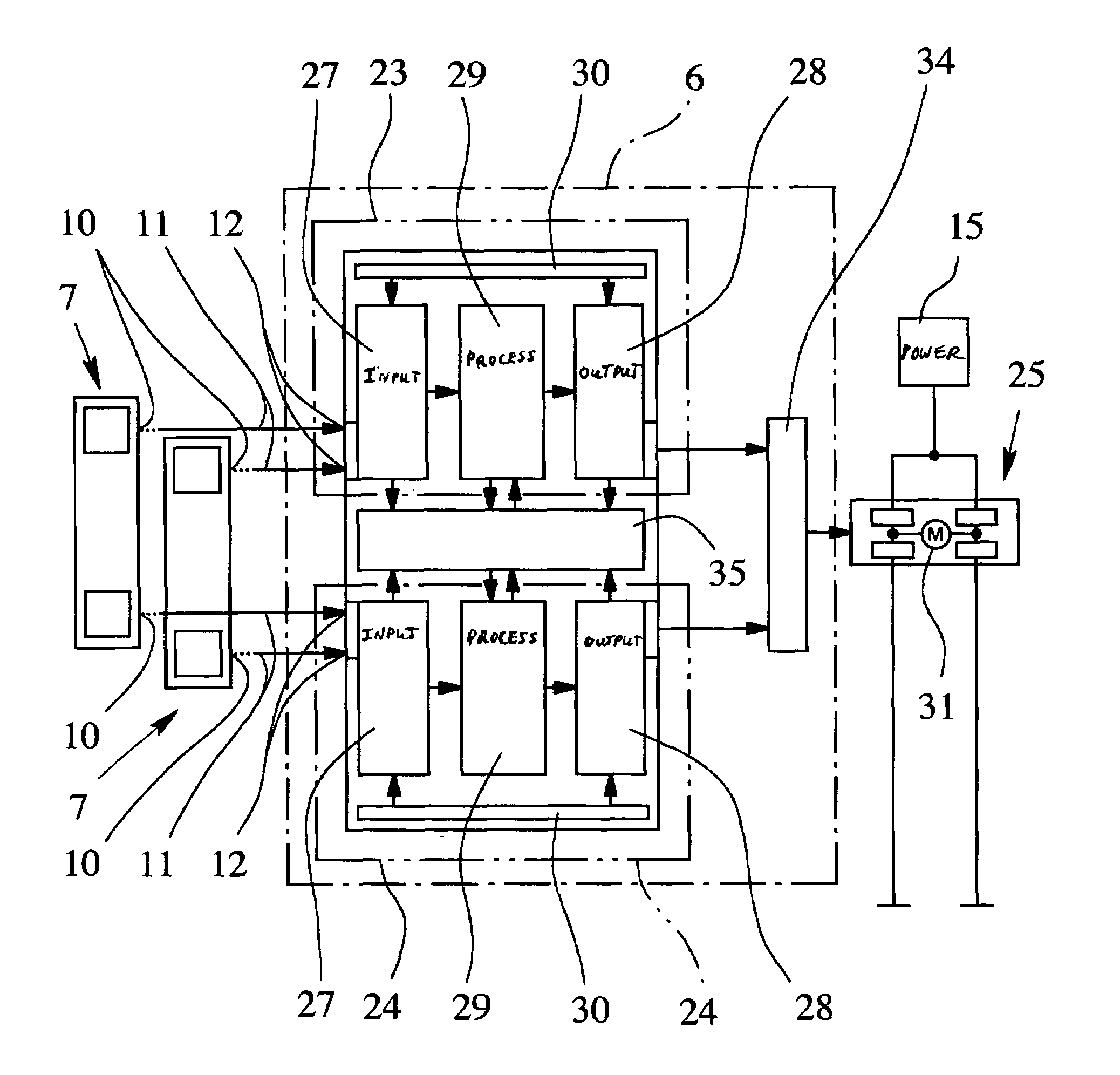
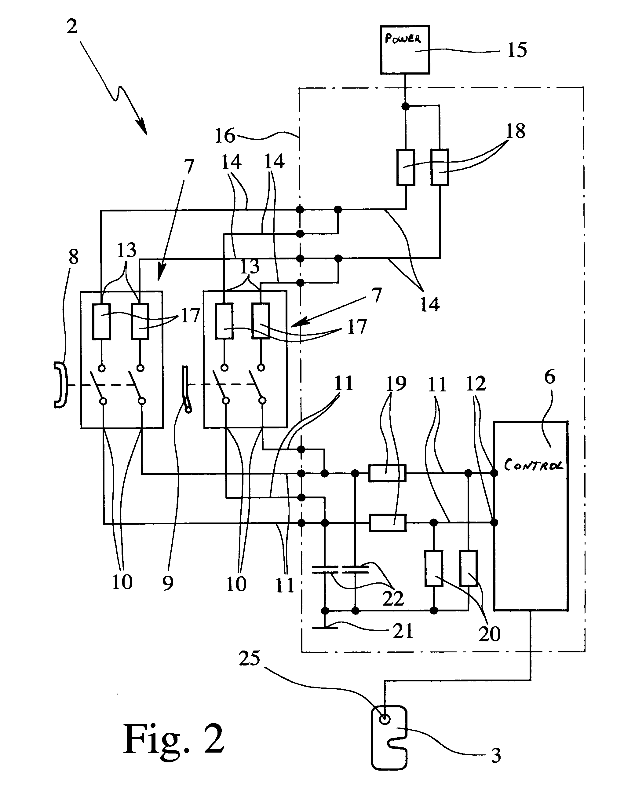
The invention is a motor vehicle with increased safety against failure or malfunction of its sensor system. This is achieved by using a sensor with two electrically independent outputs for transmission of sensor signals and connecting them to the control means via electrical signal lines. This allows detection of any interruption or malfunction of the sensor signals and ensures proper operation even in the event of failure or malfunction. The sensor can be assigned to a control element on the motor vehicle, such as a door handle or a control lever, to detect actuation of the control element and induce opening of the motor vehicle lock. The invention also includes a redundant control means with two evaluation units that evaluate the sensor signals in parallel, ensuring high safety levels even if one of the evaluation units fails.

Problems solved by technology

In the known motor vehicle locking system, there is the risk that the connection which is conventionally formed by cables between the sensor and the control means can be interrupted or short circuited, for example, as a result of a cable break, accident or the like.
This would lead to immediate failure of the sensor and thus to a safety risk since, for example, the motor vehicle door can no longer be opened.
At the same time, there is the danger of a malfunction of the sensor or the control means which, in the worst case, can lead to unwanted motorized lifting of the ratchet and thus opening of the motor vehicle door while driving.
This malfunction can be caused, for example, by electromagnetic interference fields or by a crash situation.
For an at least partially software-implemented control means, then, possibly errors in the input / output registers or unforeseeable jumps in the program execution with the corresponding unforeseeable consequences occur.

Method used


Image

  • Motor vehicle door lock system
  • Motor vehicle door lock system
  • Motor vehicle door lock system

Examples


Embodiment Construction

[0027]In the figures, for the same or different parts the same reference numbers are used, the corresponding or comparable properties and advantages being achieved, even if a repeated description is omitted.

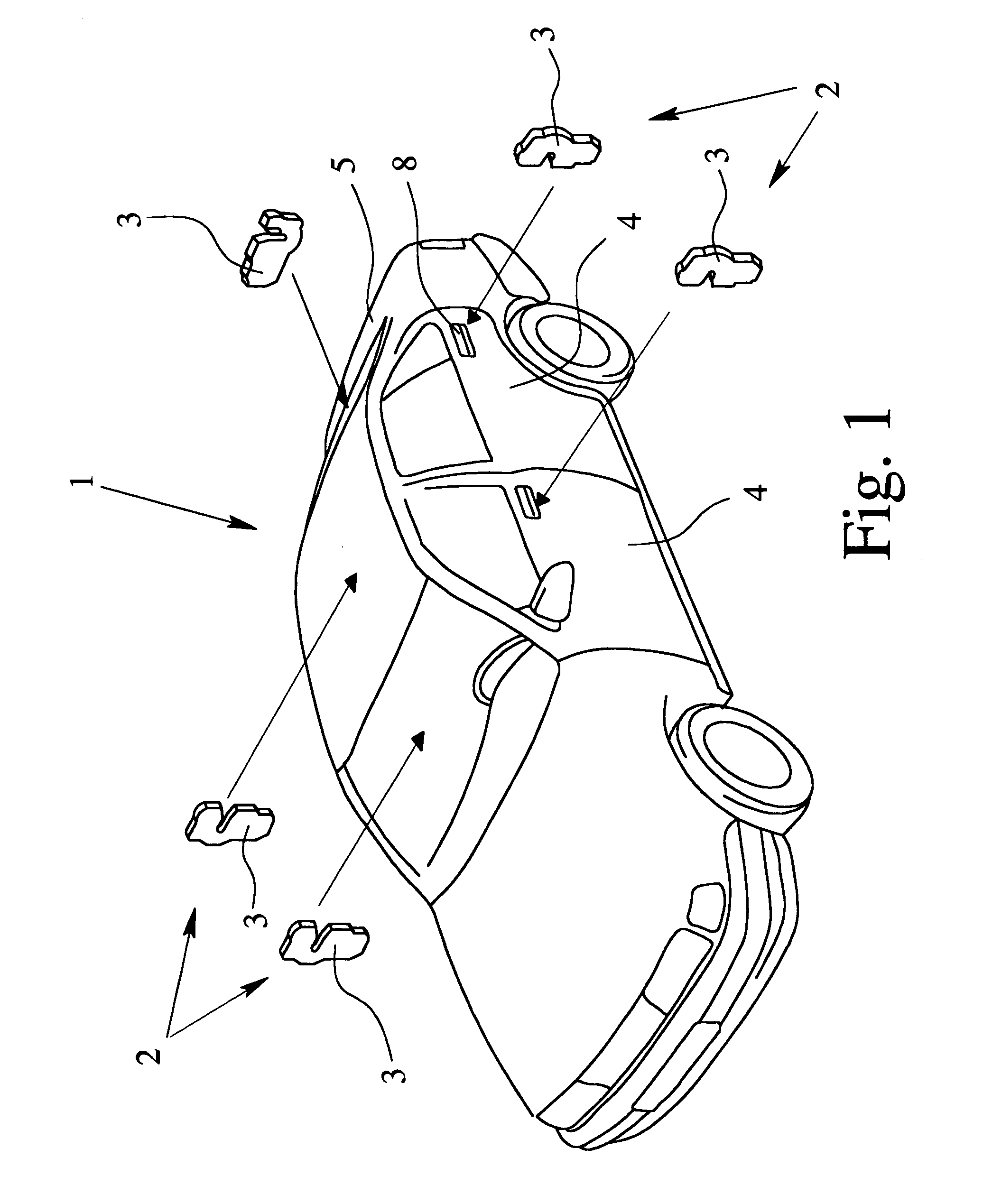
[0028]FIG. 1 schematically shows a motor vehicle 1 with a motor vehicle locking system 2, which is shown only partially. It has especially several motor vehicle locks 3, especially for side doors 4 and / or a trunk lid 5, a rear hatch, a tailgate or the like.

[0029]The expression “motor vehicle lock” is therefore defined primarily as a door lock. However, it can be a trunk lock, a hood lock, a hatch lock or the like of the motor vehicle 1.

[0030]In the illustrated embodiment, the installation positions of the motor vehicle locks 3 are shown schematically by the arrows in FIG. 1.

[0031]Each motor vehicle lock 3—at least of the side doors 4—can be electrically controlled, preferably, so as to be actuated by a motor, and especially can be locked and unlocked by an electric motor and / or c...


PUM


Abstract

A motor vehicle with a control means and an electrically connected sensor. The sensor is used especially to detect the actuation of a door handle for opening a motor vehicle lock. In order to ensure high failure safety, the sensor for transmission of sensor signals has at least two electrically independent outputs which are connected to the control means via electrical signal lines.

Description

BACKGROUND OF THE INVENTION[0001]1. Filed of Invention[0002]This invention relates to a motor vehicle with a control means and with at least one sensor which is electrically connected to the control means.[0003]2. Description of Related Art[0004]German Patent Application DE 196 32 915 A1, which corresponds to U.S. Pat. No. 5,901,991, forms the starting point of this invention and discloses a motor vehicle locking system of a motor vehicle. The motor vehicle locking system has a control means and a motor vehicle lock. The motor vehicle lock is made as a so-called electric lock in which a ratchet for opening the latch of the motor vehicle lock can be lifted by means of an electrical drive. A microswitch which is necessarily made as a double throw momentary contact switch and which is connected to the control means is assigned to the ratchet as the sensor for detecting the state of the ratchet.[0005]Furthermore, the known motor vehicle locking system has a handle, especially an outside...

Claims


Application Information

Patent Timeline
Patent Type & Authority Patents(United States)
IPC IPC(8): B60L1/00E05B17/22E05B47/06E05B65/12E05B65/20E05B65/36
CPCE05B77/04E05B81/77E05B77/48
Inventor HENTSCH, INGMARLANGFERMANN, MICHAELGROEWE, CHRISTIANHEGERFELD, FRANKDUENNE, KLAUSPLATZKOESTER, ANDREAS
Owner BROSE SCHLIESSSYSTEME GMBH & CO KG
Learn More