Substrate-guided relays for use with scanned beam light sources

a relay and beam light source technology, applied in the direction of mirrors, instruments, polarising elements, etc., can solve the problems of large and heavy display systems relying on these techniques, large size and weight of systems, and image discontinuities

Inactive Publication Date: 2009-09-15
MICROVISION
View PDF38 Cites 113 Cited by
  • Summary
  • Abstract
  • Description
  • Claims
  • Application Information

AI Technical Summary

Problems solved by technology

However, these systems require increases in size in order to expand the field of view or exit pupil expansion.
Display systems relying on these techniques are therefore large and heavy when a wide field of view is desired.
Although relays relying on this structure may provide a desirable form factor, the relays require numerous reflectors each having a different and precise reflectance characteristic, which create discontinuities in an image within the relay and images seen through the relay.
They often do not efficiently couple light out of the substrate.
A short-coming of existing substrate-guided relays is that they are not compatible with recent advances in light source technology.
Scanned beam light sources produce narrower input beams and current relays have poor efficiency and do not generate sufficient duplicates to produce a uniform image or pupil for smaller scanned beam based images.
Additional problems arise when expanding the field of view or the pupil with current relays, making the relays difficult to fabricate and manufacture.
These and other problems exist with adapting current substrate-guided relays for scanned beam light sources.

Method used


Image

  • Substrate-guided relays for use with scanned beam light sources
  • Substrate-guided relays for use with scanned beam light sources
  • Substrate-guided relays for use with scanned beam light sources

Examples


Embodiment Construction

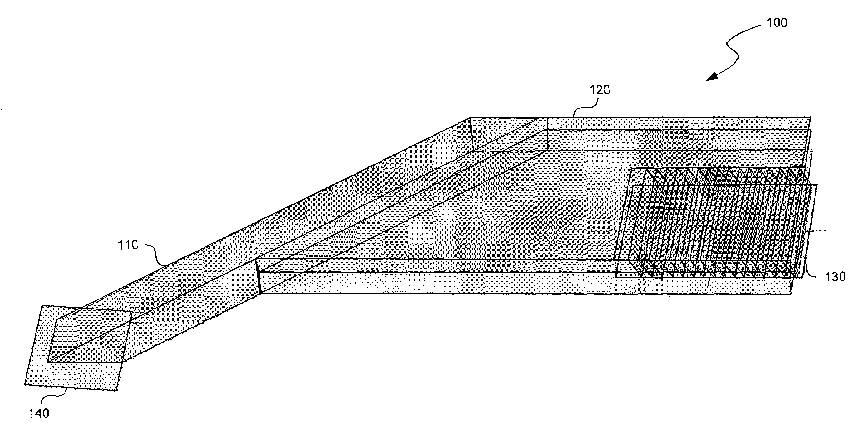
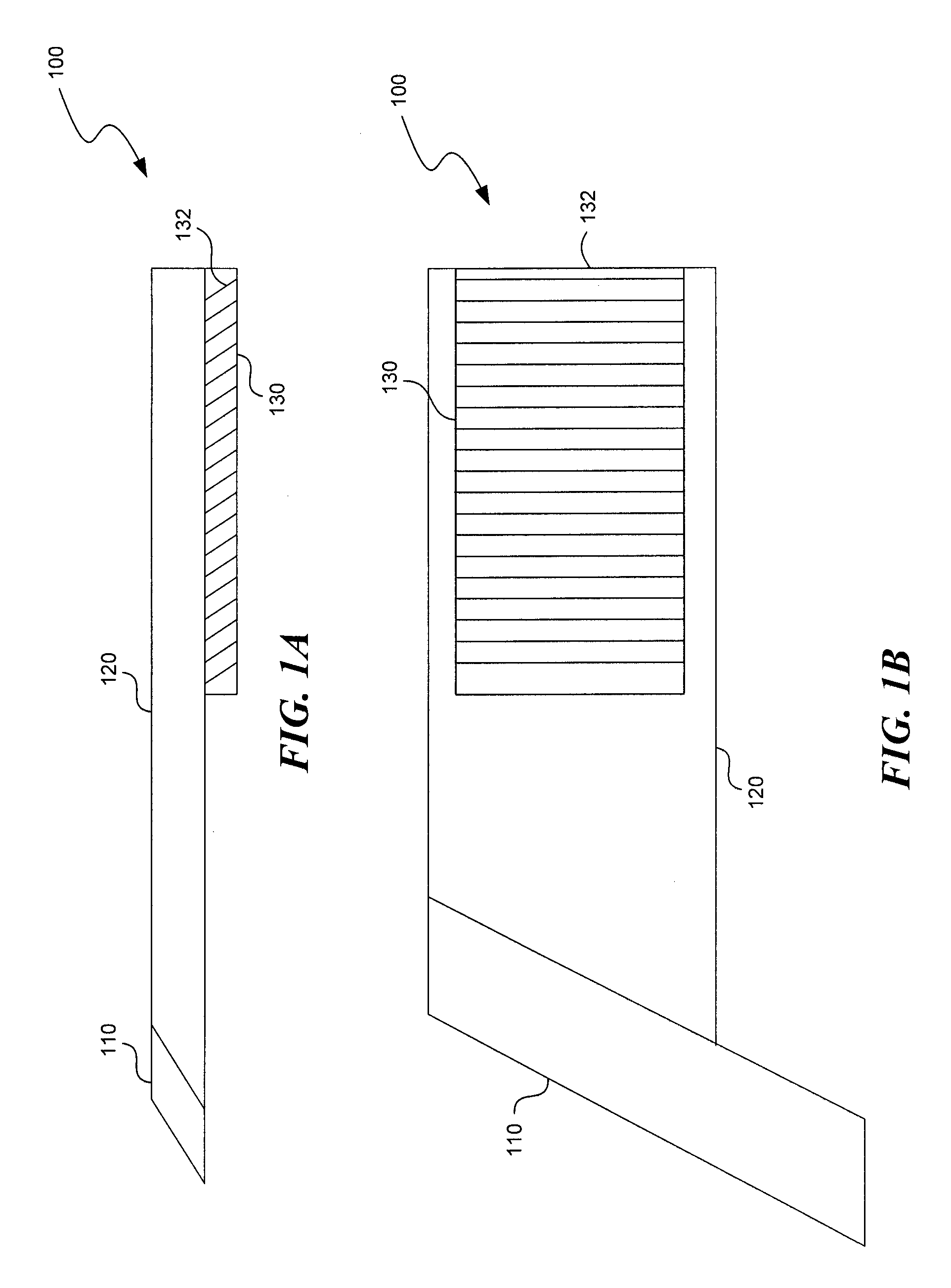
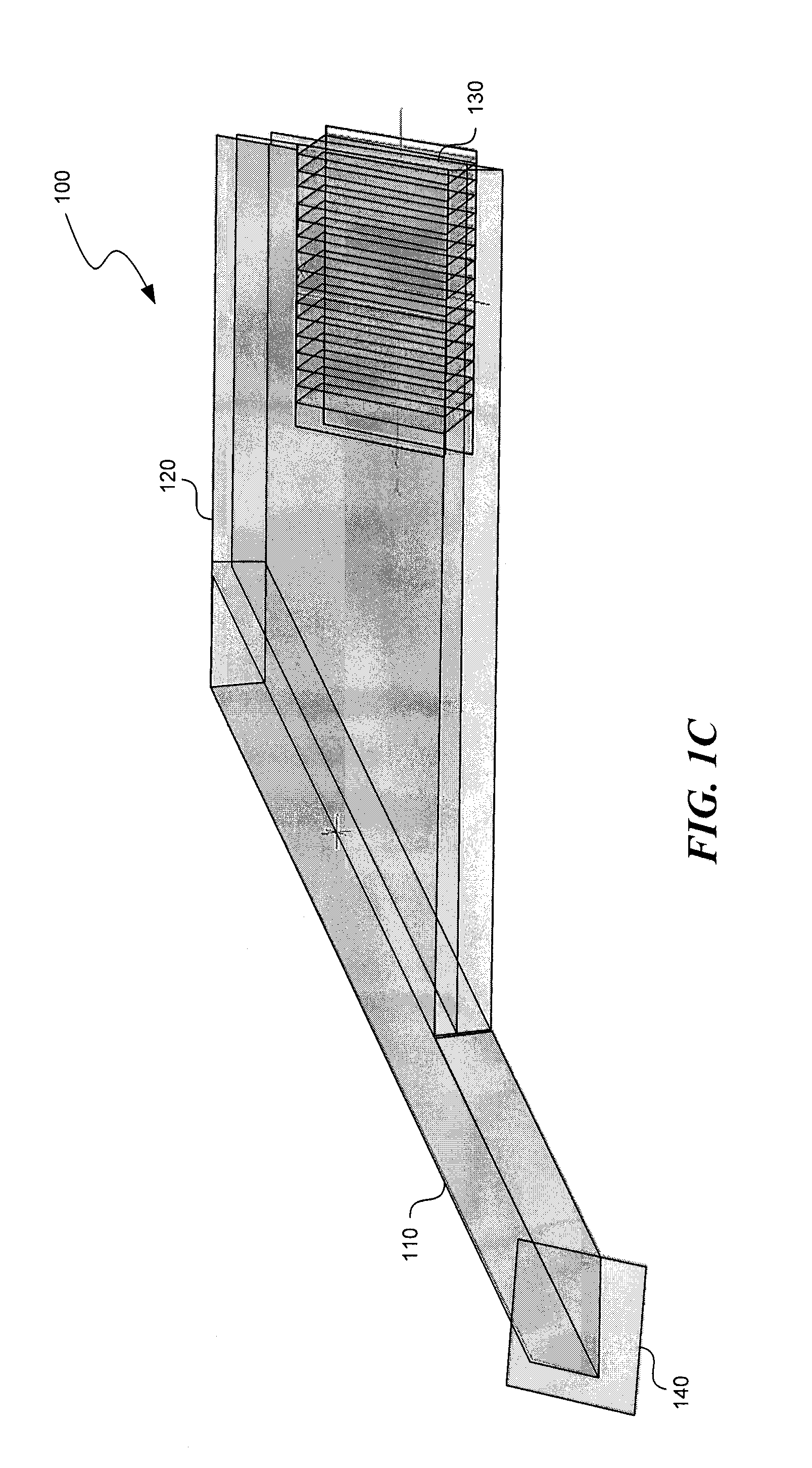
[0030]Various substrate-guided relays that employ light guiding substrates to relay images from sources to viewers in optical display systems are disclosed. The substrate-guided relays are comprised of an input coupler, an intermediate substrate, and an output coupler. In some embodiments, the output coupler is formed in a separate substrate that is coupled to the intermediate substrate. The output coupler may be placed in front of or behind the intermediate substrate, and may employ two or more partially reflective surfaces to couple light to and / or from the coupler. In some embodiments, the input coupler is coupled to the intermediate substrate in a manner that the optical axis of the input coupler intersects the optical axis of the intermediate substrate at a non-perpendicular angle. In some embodiments, the input coupler is coupled to the intermediate substrate in a manner that the optical axis of the input coupler intersects the optical axis of the intermediate substrate at a p...


PUM


Abstract

Substrate-guided relays that employ light guiding substrates to relay images from sources to viewers in optical display systems. The substrate-guided relays are comprised of an input coupler, an intermediate substrate, and an output coupler. In some embodiments, the output coupler is formed in a separate substrate that is coupled to the intermediate substrate. The output coupler may be placed in front of or behind the intermediate substrate, and may employ two or more partially reflective surfaces to couple light from the coupler. In some embodiments, the input coupler is coupled to the intermediate substrate in a manner that the optical axis of the input coupler intersects the optical axis of the intermediate substrate at a non-perpendicular angle.

Description

BACKGROUND[0001]Head-mounted and other compact display systems, such as head-up displays (HUDs), laptops, monitors, and other systems often rely on optical devices that overlay images onto transparent optical elements. For example, systems may display images through transparent lenses in front of a user's eyes to enable the user to view displayed images at the same time as viewing objects in the environment. Some of these display systems may utilize substrate-guided relays having three primary components: an input coupler, a transmission substrate, and an output coupler. Light beams or other electromagnetic waves enter the relay via the input coupler and remain confined within the relay due to total internal reflection or applied coatings. The beams are guided to the output coupler within the substrate, and the beams exit the relay via the output coupler.[0002]Various techniques may be used to insert light into substrate-guided relays. Some current systems use diffractive collimatio...

Claims


Application Information

Patent Timeline
Patent Type & Authority Patents(United States)
IPC IPC(8): G02B27/00G02B6/26
CPCG02B27/0081G02B27/0172G02B5/30G02B6/00G02B6/0023G02B2027/0125G02B6/0055
Inventor DEJONG, CHRISTIAN DEANPOWELL, KARLTON D.FREEMAN, MARK O.MILLER, JOSHUA O.
Owner MICROVISION
Why Eureka
Try Eureka