Appearance inspection apparatus for inspecting inspection piece
a technology for inspecting inspection pieces and appearance, which is applied in the direction of printed circuit testing, instruments, material analysis, etc., can solve the problems that no technology has been proposed for efficiently imaging and analysing the two surfaces of the board on which components are mounted, and achieve the effect of reducing the time required to inspect an inspection piece such as a board
- Summary
- Abstract
- Description
- Claims
- Application Information
AI Technical Summary
Benefits of technology
Problems solved by technology
Method used
Image

Examples
first embodiment
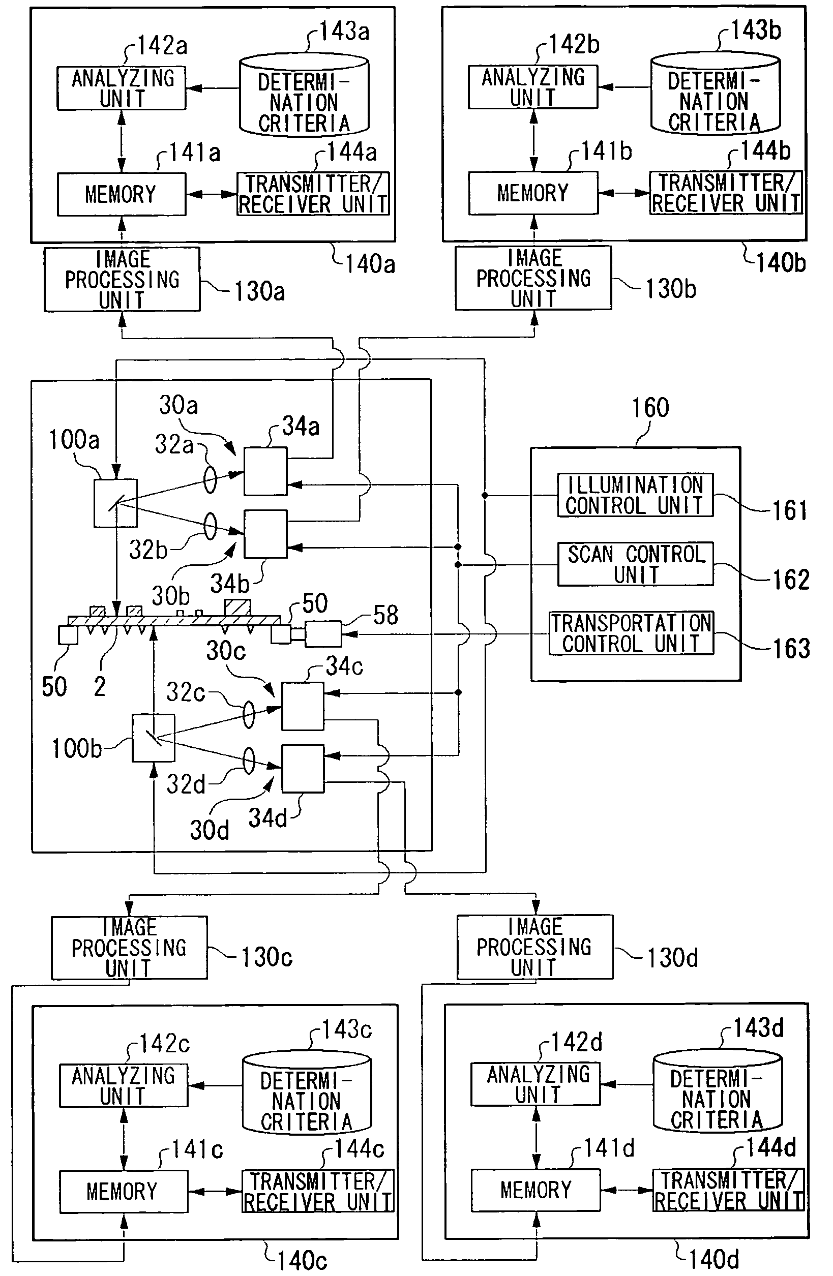
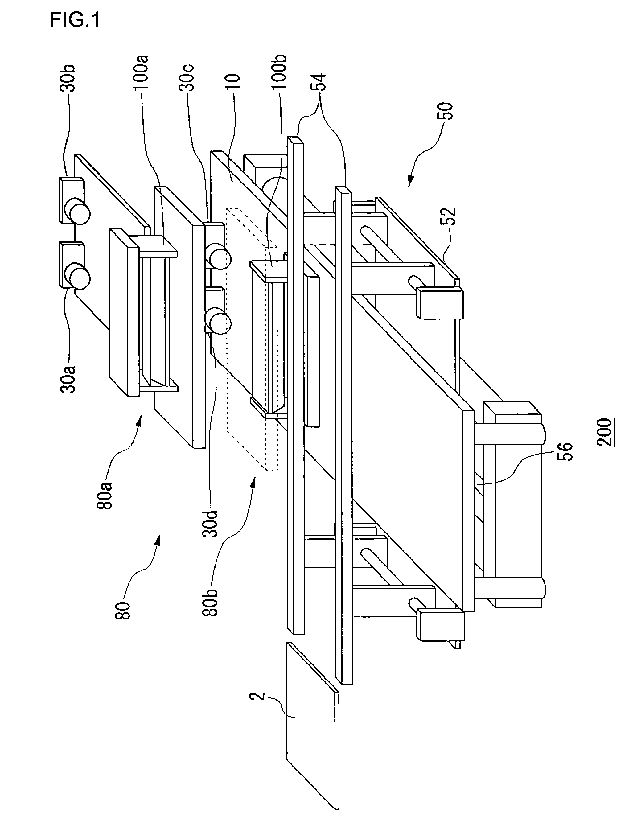
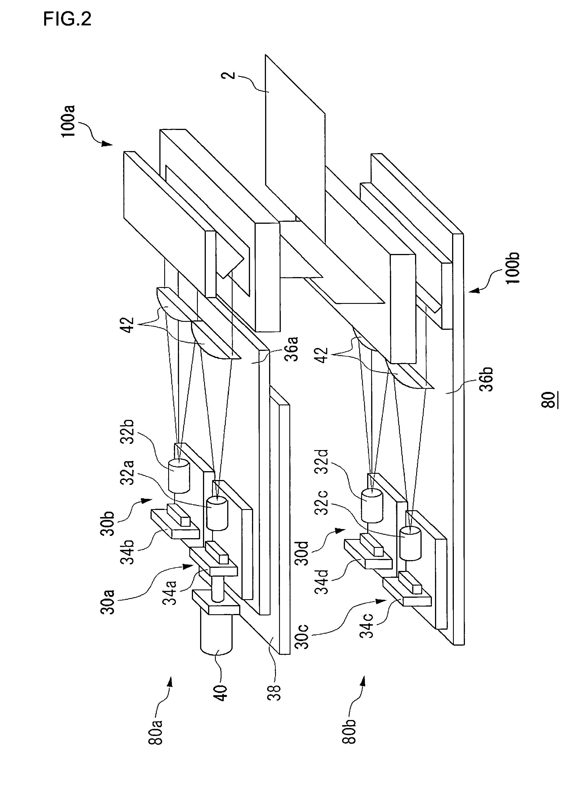
[0042]FIG. 1 shows the structure of an appearance inspection apparatus 200. The appearance inspection apparatus 200 is provided with an inspection table 10, a board transport table 50 and an imaging system 80. The board transport table 50 is provided with a support plate 52, two transport rails 54 and the like. The transport rails 54 are supported by the support plate 52.
[0043]Each of the transport rails 54 is provided with a transport belt for transporting a board 2 by driving a motor. The transport rails 54 transport the board 2 mounted on the transport belts nearly to the center of the inspection table 10. A transport sensor using a noncontact sensor such as an optical sensor (not shown) for detecting the board 2 transported is provided above the transport rails 54 and practically at the center of the inspection table. When the transport sensor detects the end face of the board 2 or a detection hole provided in the board 2, it is determined that the board 2 is transported nearly ...
second embodiment
[0085]A description will be given of a background art related to a second embodiment of the present invention. Recently, electronic boards are used in a vast majority of equipment. Miniaturization, slim size and the like are persistent goals to be achieved in equipment in which electronic boards are used. For this purposes, high-integration design of an electronic board is required. For the purpose of achieving high-density mounting on an electronic board, it is important to inspect the condition in which components are mounted on a board with high precision. In the related art, there is proposed an inspection apparatus in which image recognition technology is used to inspect a printed board (hereinafter, referred to as a “board”) on which components are already mounted with high precision (see, for example, patent document No. 3). There is also known an appearance inspection system in which multiple appearance inspection apparatuses and a personal computer (PC) for management are c...
third embodiment
[0157]A description will first be given of the background for a third embodiment of the present invention. Recently, electronic boards are used in a vast majority of equipment. Miniaturization, slim size, low price and the like are persistent goals to be achieved in equipment in which electronic boards are used. For this purposes, high-integration design of an electronic board is required. For the purpose of achieving high-density mounting on an electronic board, it is important to inspect the condition in which components are mounted on a board with high precision. In the related art, there is proposed an inspection apparatus in which image recognition technology is used to inspect a printed board (hereinafter, referred to as a “board”) on which components are already mounted with high precision. There is also known an appearance inspection system in which multiple appearance inspection apparatuses and a personal computer (PC) for management are connected to each other via a LAN, i...
PUM
 Abstract
Description
Claims
Application Information
 - R&D
- Intellectual Property
- Life Sciences
- Materials
- Tech Scout
- Unparalleled Data Quality
- Higher Quality Content
- 60% Fewer Hallucinations
Browse by: Latest US Patents, China's latest patents, Technical Efficacy Thesaurus, Application Domain, Technology Topic, Popular Technical Reports.
© 2025 PatSnap. All rights reserved.Legal|Privacy policy|Modern Slavery Act Transparency Statement|Sitemap|About US| Contact US: help@patsnap.com