Modular stimulation lead network

a module-based, lead-based technology, applied in the field of patient-specific implantation of stimulation leads, can solve problems such as lack of power efficiency, and achieve the effect of prolonging reli

Inactive Publication Date: 2009-09-15
BOSTON SCI SCIMED INC
View PDF185 Cites 74 Cited by
  • Summary
  • Abstract
  • Description
  • Claims
  • Application Information

AI Technical Summary

Benefits of technology

[0018]Preferably, the first and second stimulation leads are delivered through a percutaneous opening within the patient's skin, thereby minimizing patient discomfort and damage to otherwise healthy tissue. Although delivered in a minimally invasive manner, the larger footprint created by the coupled stimulation leads provides the assembly with more stability and greater coverage area. Thus, although not necessarily limited in its broadest aspects, the advantages of a surgical lead are retained by the present invention, without the disadvantages associated with invasive surgical procedures otherwise required to implant surgical leads.
[0020]In one preferred method, the stimulation leads are coupled to a stimulation source, in which case, the method may further comprise conveying stimulation energy (e.g., electrical energy) from the stimulation source to the stimulation leads to stimulate neural tissue within the patient's spine. The stimulation energy may be focused into the neural tissue, as opposed to conveying the stimulation energy in all radial directions. In the preferred method, the stimulation leads are implanted within the patient's spine, e.g., to provide extended relief.

Problems solved by technology

This ultimately translates into a lack of power efficiency, where percutaneous leads tend to exhaust a stimulator battery supply 25%-50% greater than that exhausted when surgical leads are used.
Although surgical leads are functionally superior to percutaneous leads, there is one major drawback—surgical leads require painful surgery performed by a neurosurgeon, whereas percutaneous leads can be introduced into the epidural space minimally invasively by an anesthesiologist using local anesthesia.

Method used


Image

  • Modular stimulation lead network
  • Modular stimulation lead network
  • Modular stimulation lead network

Examples


Embodiment Construction

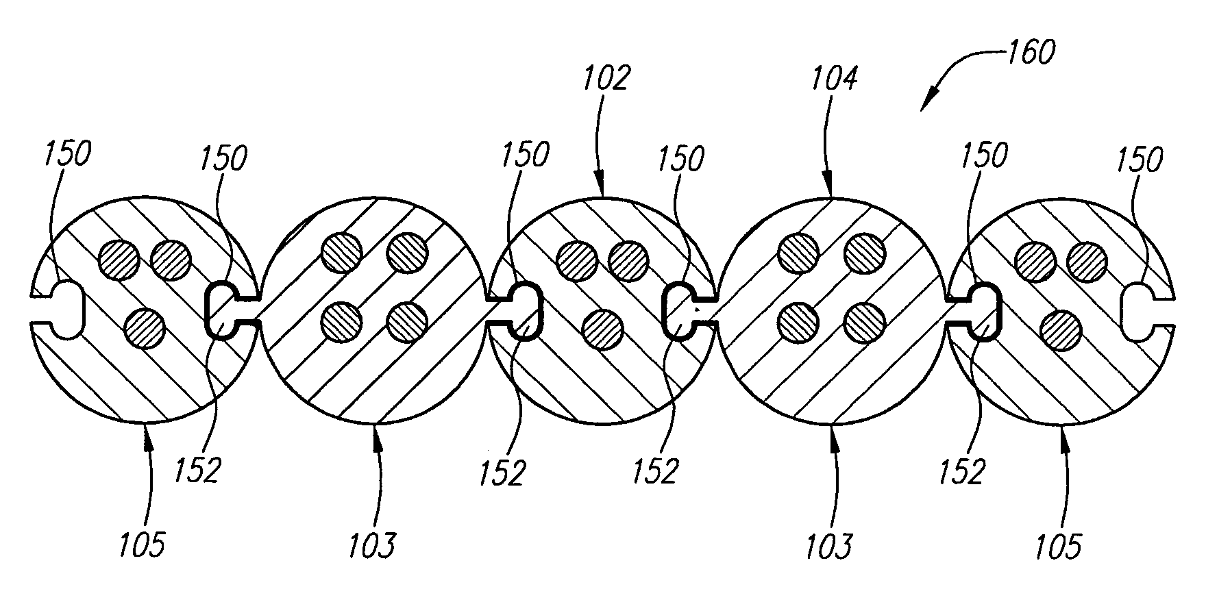
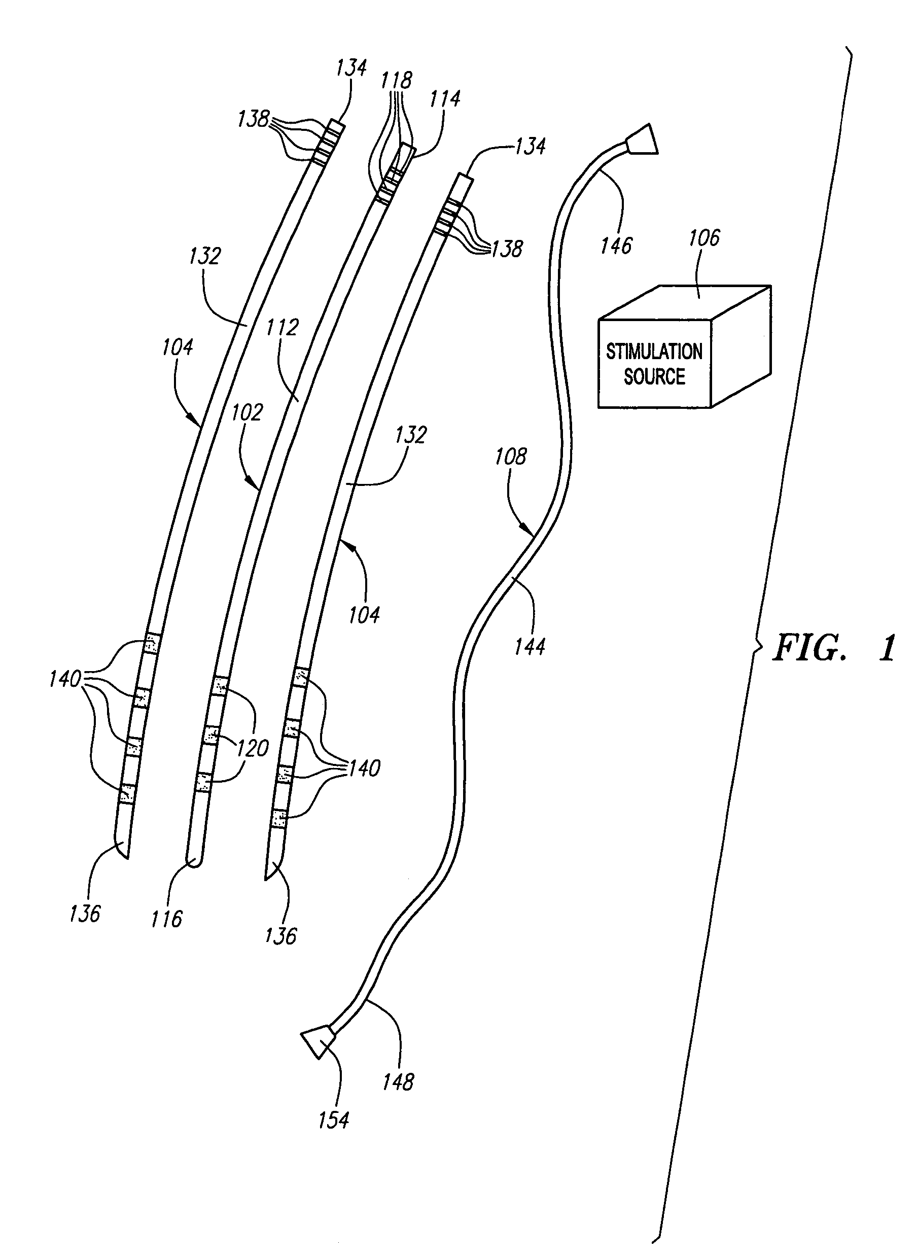
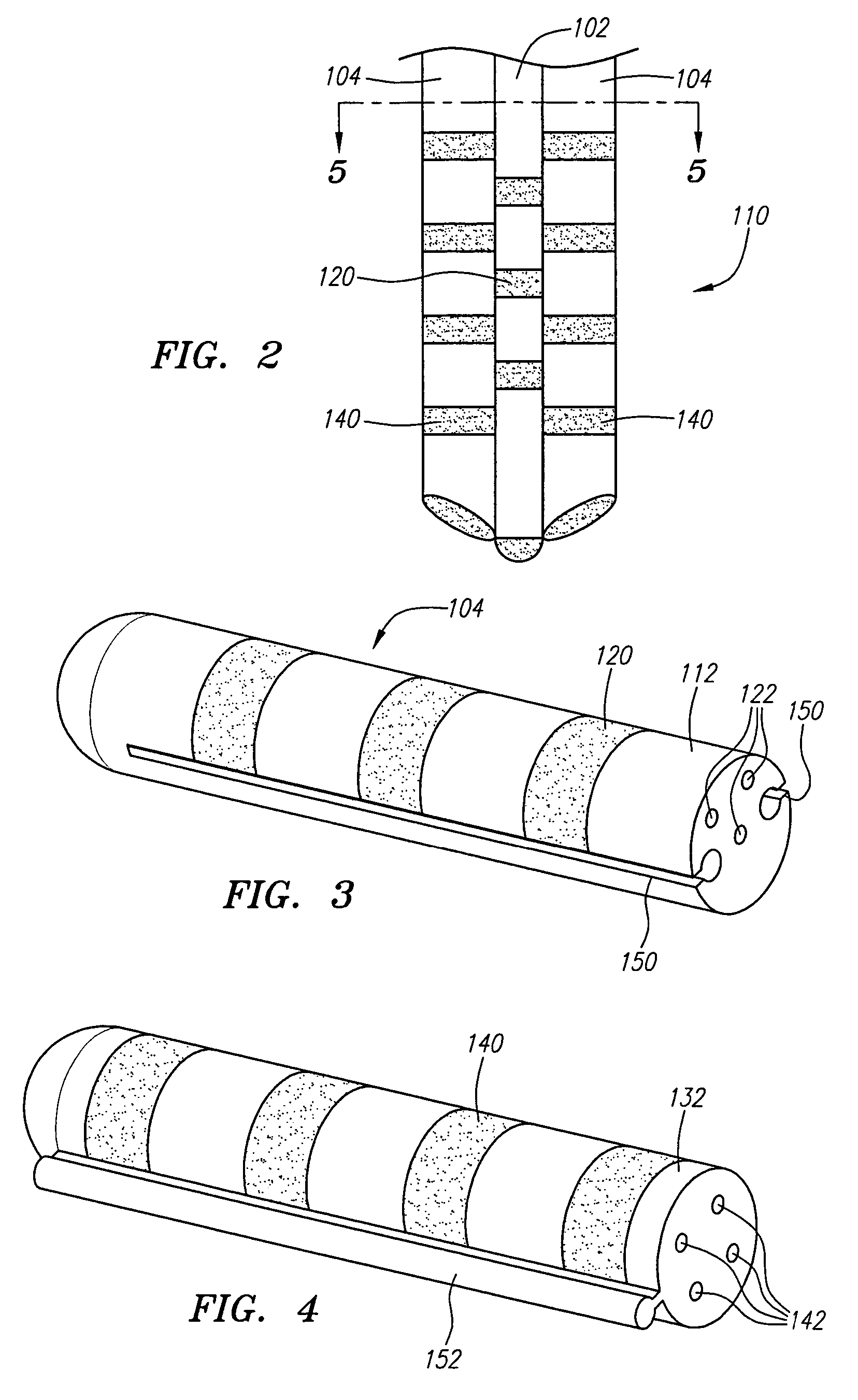
[0052]Referring now to FIG. 1, a modular stimulation lead kit 100 arranged in accordance with one preferred embodiment of the present invention is shown. In its simplest form, the stimulation kit 100 generally comprises a primary stimulation lead 102 and two secondary stimulation leads 104, which are configured to be percutaneously delivered and implanted into the epidural space of a patient's spine, an implantable electrical stimulation source 106 configured for delivering stimulation energy to the stimulation leads 102 / 104, and an optional extension lead 108 configured for connecting the stimulation leads 102 / 104 to the remotely implanted stimulation source 106. As will be described in further detail below, the secondary stimulation leads 104 can be attached to the primary stimulation lead 102 to form a modularized stimulation lead assembly 110, as illustrated in FIG. 2.

[0053]It should be noted that although the kit 100 illustrated in FIG. 1 is described herein as being used in sp...


PUM


Abstract

A medical kit and method for treating an ailment, such as chronic pain is provided. The kit comprises first and second medical leads, e.g., stimulation leads. Each lead comprises an elongated body and at least one operative element. The first medical lead comprises a coupling mechanism, such as a slot, and the second medical lead comprises a complementary mechanism, such as a rail, that slidably engages the coupling mechanism of the first medical lead. The method may comprise delivering the first medical lead into a patient's body, e.g., into the epidural space of the patient, and delivering the second medical lead into the patient's body by sliding the complementary coupling mechanism of the second medical lead along the coupling mechanism of the first medical lead.

Description

FIELD OF THE INVENTION[0001]The invention relates to the implantation of stimulation leads within a patient, and in particular, the implantation of electrode leads within a patient's spine to treat disorders, such as chronic pain.BACKGROUND OF THE INVENTION[0002]It is known to treat chronic pain by electrically stimulating the spinal cord, spinal nerve roots, and other nerve bundles. Although not fully understood, the application of electrical energy to particular regions of the spinal cord induces parasthesia (i.e., a subjective sensation of numbness or tingling) in the afflicted body regions associated with the stimulated spinal regions. This parasthesia effectively masks the transmission of chronic pain sensations from the afflicted body regions to the brain. Since each body region is associated with a particular spinal nerve root, it is important that stimulation be applied at the proper longitudinal position along the spinal cord to provide successful pain management and avoid ...

Claims


Application Information

Patent Timeline
Patent Type & Authority Patents(United States)
IPC IPC(8): A61N1/34A61N1/04A61N1/05A61N1/36
CPCA61N1/0551A61N1/36071A61N1/36021A61N1/36017
Inventor GARABEDIAN, ROBERT J.WALLACE, MICHAEL P.
Owner BOSTON SCI SCIMED INC
Why Eureka
Try Eureka