Electromagnetic valve

a technology of electromagnetic valves and diaphragms, applied in the direction of spindle sealing, spindle operating means/release devices, transportation and packaging, etc., can solve the problems of reducing the control response performance of electromagnetic valves, reducing the durability of elastically deforming portions, and reducing the endurance and reliability of electromagnetic valves. , to achieve the effect of reducing operational noise, increasing the size of the effect of the operation and reliability

Inactive Publication Date: 2009-09-22
DENSO CORP
View PDF10 Cites 35 Cited by
  • Summary
  • Abstract
  • Description
  • Claims
  • Application Information

AI Technical Summary

Benefits of technology

[0009]The present invention is achieved in view of the above-described issues, and has an object to provide an electromagnetic valve that can decrease an operational noise by a damper effect in an axial extending and shrinking motion of the cylindrical bellows portion of the bellows without decreasing an endurance and reliability and increasing a size thereof.

Problems solved by technology

Accordingly, the electromagnetic valve has such an issue that the moving core and the valve element generate operational noises of when the moving elements come in contact with the stopper or the valve seat in both a valve-opening operation time and a valve-closing operation time.
Thus, the durability of the elastically deforming portion decreases, so that a crack may generate on the diaphragm to tear the diaphragm.
However, the hard elastically deforming portion is not easily deformed, to decrease a control response performance of the electromagnetic valve.
It is also considered to increase a radius of the elastically deforming portion, however, the dimensions of the housing must be changed in accordance with the upsizing of the diaphragm, and this decreases the mountability of the electromagnetic valve in an engine room of the vehicle and the like.
Thus, when the cylindrical bellows portion of the bellows shrinks in accordance with a displacement of the moving core and the valve shaft to the one side in the axial direction, the fluid filled in the inner space of the cylindrical bellows portion is discharged at a stroke through the communication passage to the side of the fluid passage, to cause an issue that the electromagnetic valve does not generate enough damper effect as in the above-mentioned electromagnetic valve provided with the diaphragm.

Method used


Image

  • Electromagnetic valve
  • Electromagnetic valve
  • Electromagnetic valve

Examples


first embodiment

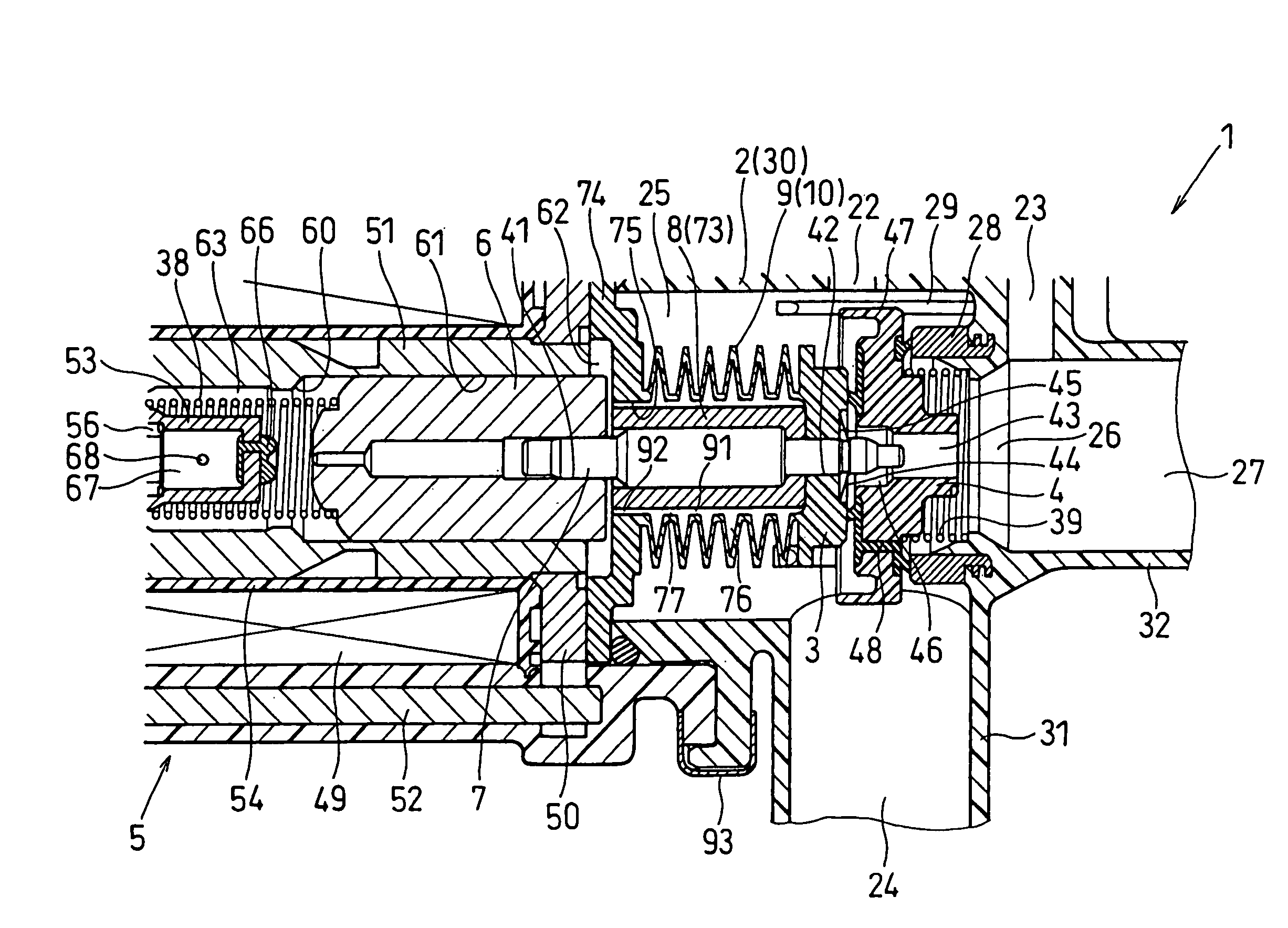
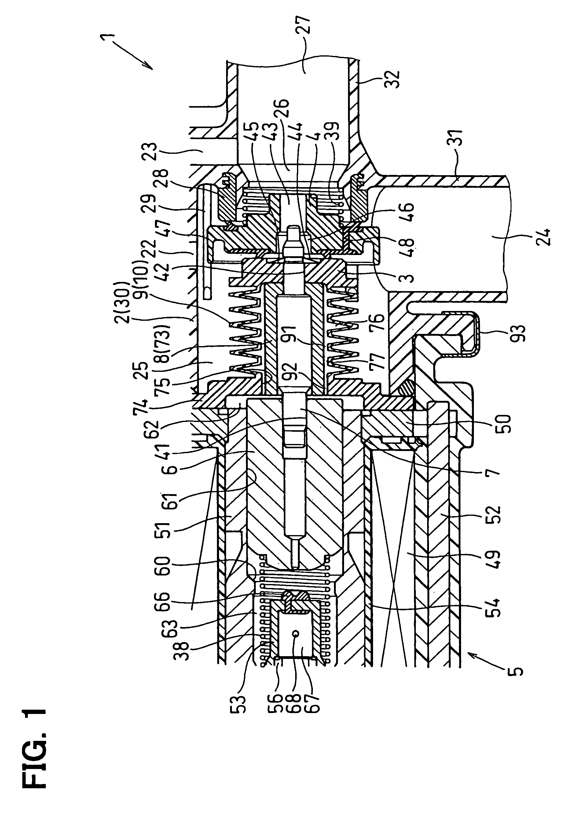
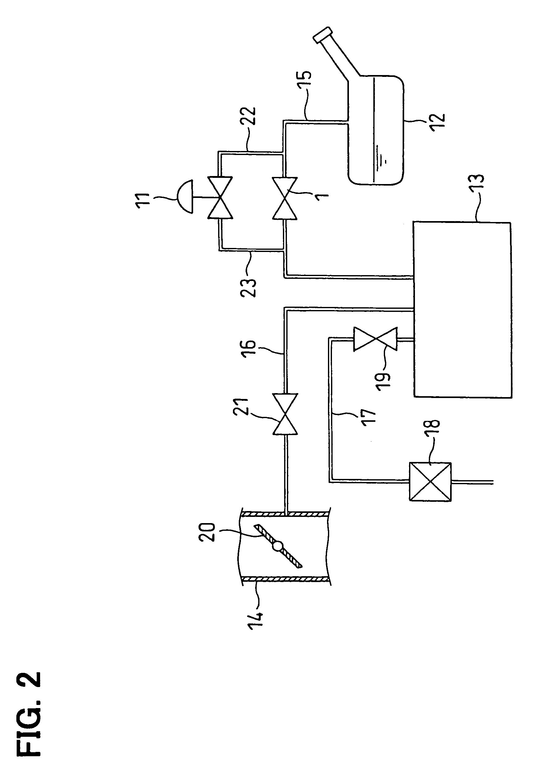
[0022]In a first embodiment of the present invention, an electromagnetic valve 1 is incorporated in an evaporative emission control system together with a relief valve 11. The electromagnetic valve 1 serves as an electromagnetic tank-sealing valve. The electromagnetic tank-sealing valve includes a normally-closed electromagnetic opening / closing valve, which opens for a predetermined period while the vehicle is traveling and at a time just before a fuel tank 12 is refueled and closes at all other times, and a pressure-operated pressure control valve (pressure-sensing valve). The evaporative emission control system is a vaporized fuel (evaporated gas) fly-off prevention system that prevents fluid such as vaporized fuel from flying off into the atmosphere by recovering the fluid such as vaporized fuel, which is vaporized (volatilized) in the fuel tank 12 of the vehicle, through a canister 13 into an engine intake pipe 14 of an internal combustion engine (hereinafter referred to as engi...

second embodiment

[0075]In an electromagnetic valve 1 according to a second embodiment shown in FIG. 5, an outer diameter of the sleeve portion 73 of the retainer 8 is partially decreased. That is, the sleeve portion 73 of the retainer 8 includes a small diameter portion 73a and a flange portion 73b having a diameter larger than that of the small diameter portion 73a. The small diameter portion 73a is at a right side (in FIG. 5) of a step of the sleeve portion 73 to face the inner circumference of the trough portion of the cylindrical bellows portion 10 of the bellows member 9. The flange portion 73b is at a left side (in FIG. 5) of the step of the sleeve portion 73 to face the inner circumference of the flange portion 74 or the opening portion 75 of the bellows member 9. Accordingly, the cylindrical air passage (radially inside space) 77, which is defined between the small diameter portion 73a of the sleeve portion 73 of the retainer 8 and the cylindrical bellows portion 10 of the bellows member 9, ...

third embodiment

[0076]In an electromagnetic valve 1 according to a third embodiment shown in FIG. 6, an outer diameter of a large diameter portion 79 of the valve shaft 7 is large relative to that in the first embodiment. Accordingly, it is possible to decrease the inner volume of the cylindrical air passage (radially inside space) 77, which is defined between the large diameter portion 79 of the valve shaft 7 and the cylindrical bellows portion 10 of the bellows member 9, without the retainer 8 in the first embodiment. Thus, it is possible to provide the inner space of the cylindrical bellows portion 10 of the bellows member 9 with a plurality of the aperture portions 91. Further, it is possible to provide one aperture portion 92 between the opening portion 75 of the bellows member 9 and the large diameter portion 79 of the valve shaft 7. Accordingly, the electromagnetic valve 1 according to the third embodiment serves substantially the effects as in the first embodiment.


PUM


Abstract

In an electromagnetic valve, a valve member is slidably installed in a housing to open and close a valve hole. A moving core is slidably installed in the housing, and a coil generates a magnetomotive force to attract the moving core to one side when it is energized. The valve shaft links a motion of the moving core with a motion of the valve member. A bellows surrounds the valve shaft to form a cylindrical inner space between the valve shaft and itself. The bellows is subjected to both positive and negative pressures to extend and shrink in accordance with the motions of the valve member and the moving core. An inner volume of the inner space increasing and decreasing in accordance with extending and shrinking operations of the cylindrical bellows portion. The opening of the bellows and the valve shaft form a narrow opening passage.

Description

CROSS REFERENCE TO RELATED APPLICATION[0001]This application is based upon and claims the benefit of priority of Japanese Patent Application No. 2005-073527 filed on Mar. 15, 2005, the content of which is incorporated herein by reference.FIELD OF THE INVENTION[0002]The present invention relates to an electromagnetic valve having a cylindrical bellows that extends and shrinks in its axial direction and in which a damper effect generated by a narrow opening portion of the bellows reduces an operational noise of a moving core and / or a valve element, and especially relates to the electromagnetic valve such as an electromagnetic tank-sealing valve in which both positive pressure larger than the atmospheric pressure and negative pressure smaller than the atmospheric pressure alternately act onto the valve and bellows.BACKGROUND OF THE INVENTION[0003]Conventionally, an electromagnetic flow amount control valve (electromagnetic valve) is put forth that is provided with: a housing that has a...

Claims


Application Information

Patent Timeline
Patent Type & Authority Patents(United States)
IPC IPC(8): F16K47/02F16K31/06
CPCF16K31/0655F16K41/10F16K31/0693Y10T137/7782B60K2015/03514B60K15/03519
Inventor TSUGE, SHIGETO
Owner DENSO CORP
Why Eureka
Try Eureka