Simplified rear suspension for a bicycle or the like

a rear suspension and bicycle technology, applied in the field of bicycle suspension systems, can solve the problems of reducing the effectiveness of shock absorption, enhancing rigidity, and reducing the weight of prior art rear suspension bicycle frame arrangements, and achieves the effects of reducing stiction, increasing shock absorption, and widening the force vector

Inactive Publication Date: 2009-09-22
CALFEE CRAIG
View PDF16 Cites 15 Cited by
  • Summary
  • Abstract
  • Description
  • Claims
  • Application Information

AI Technical Summary

Benefits of technology

[0015]According to one aspect of the invention, the low friction guide is a spherical component which accommodates a relatively large range of force vectors. Furthermore, contact surface area between the portions of the system sliding relative to one another are minimized. Thus, stiction is reduced and shock absorption increased as compared to the prior art.
[0016]Furthermore, the low friction guide member is robust (for example, as compared to relatively thin disks), and the accommodation for a large range of force vectors means fewer points of failure as compared to the prior art.
[0017]In addition, the system comprises a minimum of parts and a simple set up and replacement process. And, most elements of the frame are of standard type and are assemble by standard processes (e.g., no special chainstay arrangements, no special methods of attaching stays to the bottom bracket or dropouts, etc.) Thus, the need for the specialized and / or complex parts is reduced, thus reducing the cost and increasing the dependability of the system as well as minimizing weight added by the suspension system.

Problems solved by technology

The majority of prior art rear-suspension bicycle frame arrangements have suffered from excessive weight, excessive complexity, or both.
One problem with current pivotless suspension frames is a need to provide enhanced rigidity during shock absorption.
First, in any such system there will be a tendency of the sliding members to resist sliding, thus reducing the effectiveness of the shock absorption.
This may be due to tightness of fit between components, dirt, rust, fluid or other material between the bearing and the inner wall of the tube in which it travels, pinching due to force applied off-axis to the angle of motion of the bearing (such as side deflection and torque), etc.
The linear arrangement of the bearing according to U.S. Pat. No. 7,168,726 is very susceptible to stiction caused by of axis forces.
Any such off-axis forces tend to cause the bearing to pinch inside the second part of the wishbone.
Fabricating same for such an application means higher cost and more limited availability of such parts.
Further, the structure of the bearing, comprised of parallel disks and a hollow connecting shaft, introduce several points of failure.
The high force per surface area of this arrangement increases the likelihood of failure.
Exacerbating this problem is the fact that the design requires a hole be provided in, and perpendicular to the axis of, the bolt holding the assembly together.
This hole is a point of high stress during combined shock absorption and braking, thus another point of potential failure of the system.
Any of these failure modes could introduce the dangerous condition of the rear wheel being inadequately supported by the stay arrangement.
This limits the extent of shock absorbing motion (travel) available to the rear wheel.
Second, in addition to the unique seatstay arrangement, the shock absorber requires numerous specialized parts.
Such a shock absorber is expensive, heavy, and difficult to service.
And as the number of elements increase, the chances of breakage or part failure increase.
Third, the shock absorber is of the oil-filled type, requiring specialized maintenance skills, parts, tools, etc.

Method used


Image

  • Simplified rear suspension for a bicycle or the like
  • Simplified rear suspension for a bicycle or the like
  • Simplified rear suspension for a bicycle or the like

Examples


Embodiment Construction

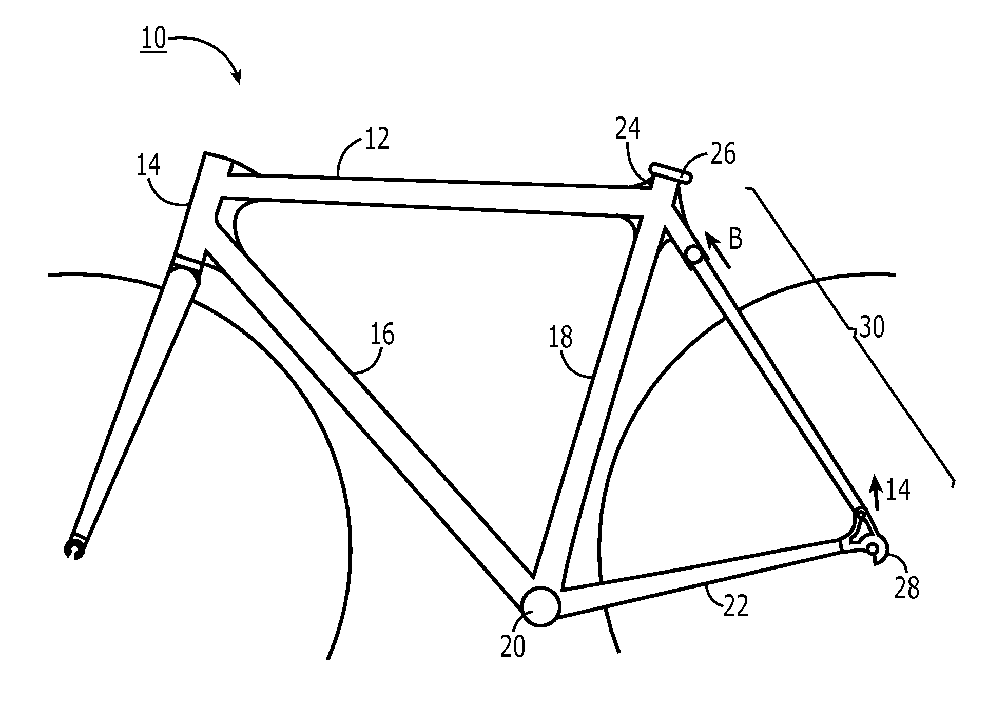
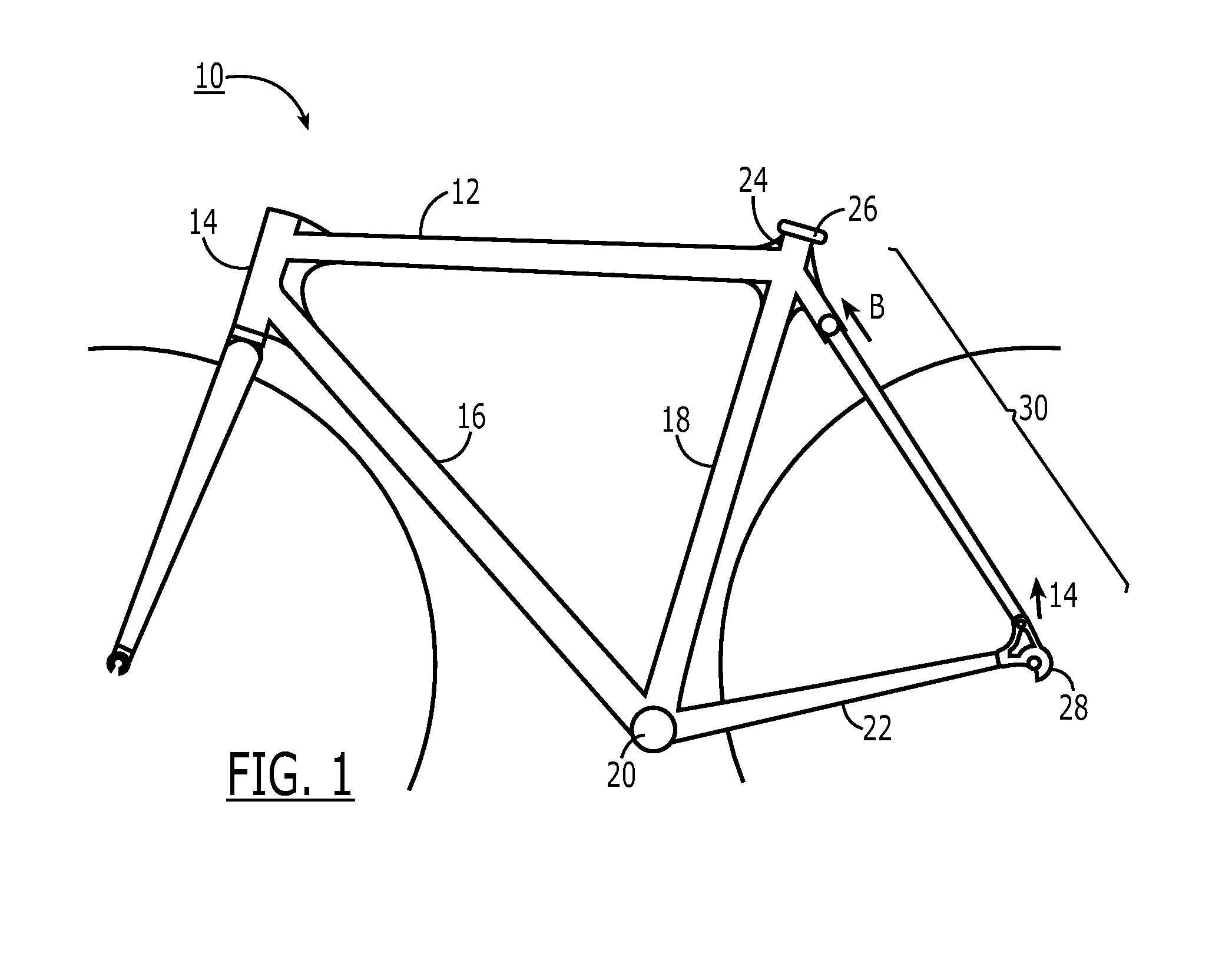
[0026]With reference first to FIG. 1, a bicycle frame 10 (or similar structure) is comprised of a top tube 12 connected to a head tube 14, which is in turn connected to a down tube 16. Down tube 16 and a seat tube 18 are connected via a bottom bracket structure 20. Seat tube 18 and top tube 12 connect at a seat junction 24 such that a seat post (not shown) may be introduced into seat tube 18 and clamped in place by a clamping mechanism 26. A pair of chainstay tubes 22 are connected at a first end to bottom bracket structure 20, and at a second end to rear wheel dropouts 28. Connecting seat junction 24 and rear wheel dropout assembly 28 is seatstay arrangement 30. Optionally, chainstay tubes 22 are removably connected to rear wheel dropouts 28.

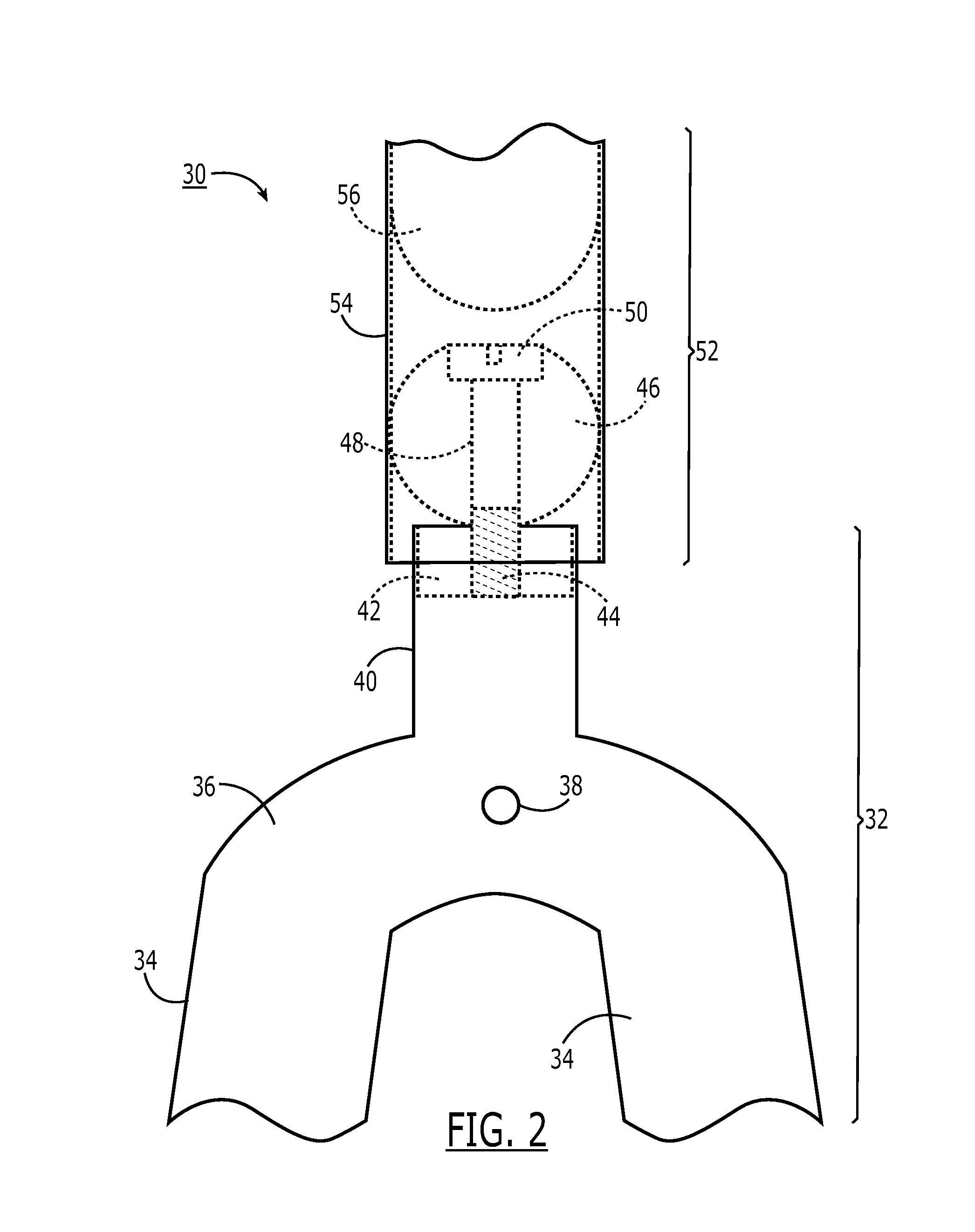
[0027]With reference now to FIGS. 2 and 3, seatstay arrangement 30 comprises a first portion 32, which is essentially a wishbone having a pair of seatstay tubes 34 connected together at a first end by a crown 36, and connected, preferably remov...


PUM


Abstract

A simplified rear suspension for a bicycle or the like comprises a wishbone seatstay structure. The wishbone structure is provided with a first extension extending toward the seat junction. A low friction guide component, for example a spherical element, is provided at the distal end of the extension. A second extension is provided at the seat junction, with a hollow interior for receiving the guide component. The guide component slides with little friction and play within the hollow interior. A stop member may also be provided within the hollow interior, stopping travel of the guide component under load. Motion of the rear wheel (via dropout) relative to the main frame (e.g., from the terrain) is translated into motion of the guide component within the hollow interior. The chainstays, in a pivotless arrangement, provide a moment which acts as a spring, resisting the motion of the dropouts and providing shock absorption and/or damping for improved ride and control.

Description

CROSS REFERENCE TO RELATED APPLICATIONS[0001]The present disclosure relates to U.S. provisional patent application Ser. No. 60 / 940,180, titled “Simplified Rear Suspension for a Bicycle or the Like”, filed May 25, 2007, which is incorporated by reference herein and to which priority is hereby claimed.BACKGROUND OF THE INVENTION[0002]1. Field of the Invention[0003]The present invention is related to bicycle suspension systems, and more specifically to a simplified suspension employing an axially moveable seat-stay arrangement with chainstays operating as a spring / dampener.[0004]2. Description of the Prior Art[0005]There are many known bicycle frame designs which provide a degree of damped motion to the rear wheel, so that transmission of sudden dips, bumps, and terrain variations to the rider via the bicycle frame are reduced. These designs generally comprise a rigid main frame (the seat tube—top tube—head tube—down tube “diamond”) with a pivoting swing arm assembly comprising the sea...

Claims


Application Information

Patent Timeline
Patent Type & Authority Patents(United States)
IPC IPC(8): B62D3/02
CPCB62K25/04
Inventor CALFEE, CRAIG
Owner CALFEE CRAIG
Why Eureka
Try Eureka