Three-phase permanent magnet brushless motor

a permanent magnet, three-phase technology, applied in the direction of rotating magnets, magnetic circuits characterised by magnetic materials, synchronous machines with stationary armatures, etc., can solve the problem of increasing cogging torque, motors generating smaller cogging torques, and no guarantee that products of the same performance can be provided every time, so as to reduce the size, improve efficiency, and eliminate quality variations

Inactive Publication Date: 2009-09-22
JAPAN SERVO CO LTD +2
View PDF13 Cites 7 Cited by
  • Summary
  • Abstract
  • Description
  • Claims
  • Application Information

AI Technical Summary

Benefits of technology

[0008]In view of the problems of the prior art mentioned above, it is an object of the present invention to provide a three-phase permanent magnet brushless motor which is capable of restraining variations in dimensions and magnetic properties associated with the manufacturing to limit an increase in cogging torque caused by variations associated with the manufacturing.
[0013]The three-phase permanent magnet brushless motor according to the present invention substantially eliminates variations in quality, can be reduced in size and improve the efficiency, and has a cogging torque reduction property. Accordingly, the motor can contribute to a reduced size, an improved efficiency, a better operability, an improved controllability and the like in applications such as automobile, home electronics, industrial driving system and the like when the motor is used in such applications.

Problems solved by technology

These motors, though generating smaller cogging torques, are inferior in energy conversion efficiency to motors based on permanent magnets.
However, in a motor which relies on the use of a high energy product magnet to reduce the size and improve the efficiency, even if a motor is optimally designed using the combination of the number of poles with the number of slots as shown Japanese Patents Nos. 2954552 and 2743918, a lower dimensional accuracy caused by variations associated with the manufacturing can result in an increase in cogging torque.
Such variations also vary depending on particular manufacturing conditions, so that there is no guarantee that products of the same performance can be provided every time.
In applications in which the cogging torque is preferably reduced to an extreme, and in applications which require motors in homogeneous specifications, variations in cogging torque due to such variations associated with the manufacturing are not welcome in many cases.

Method used


Image

  • Three-phase permanent magnet brushless motor
  • Three-phase permanent magnet brushless motor
  • Three-phase permanent magnet brushless motor

Examples


Embodiment Construction

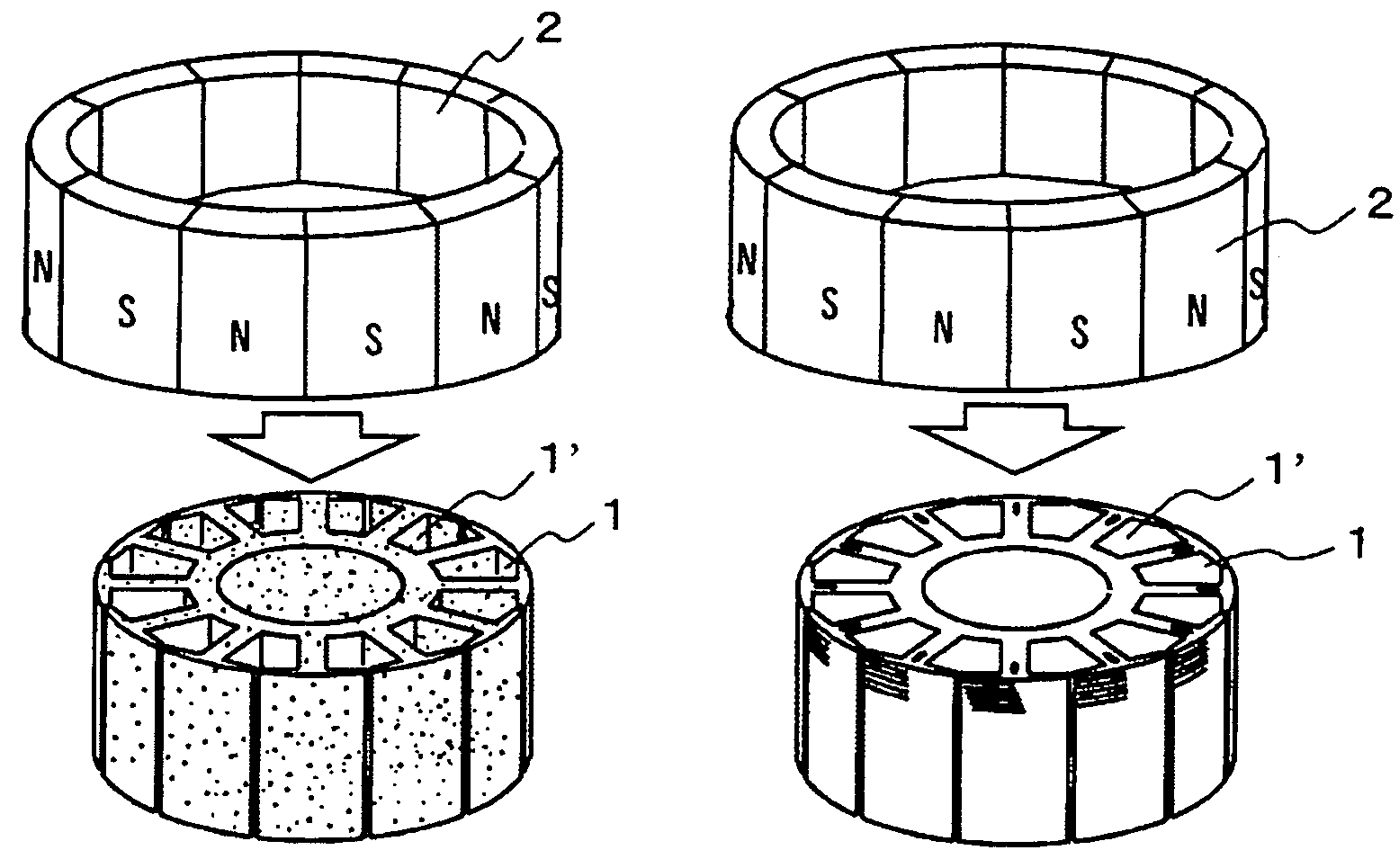
[0021]A three-phase permanent magnet brushless motor has a highly dense powder stator core and satisfies a relationship between the number of magnetic poles and the number of slots in which a cogging torque is reduced, with the intention to simultaneously achieve two contradictory objects of improving the efficiency and a cogging torque reduction performance, and reducing variations associated with the manufacturing.

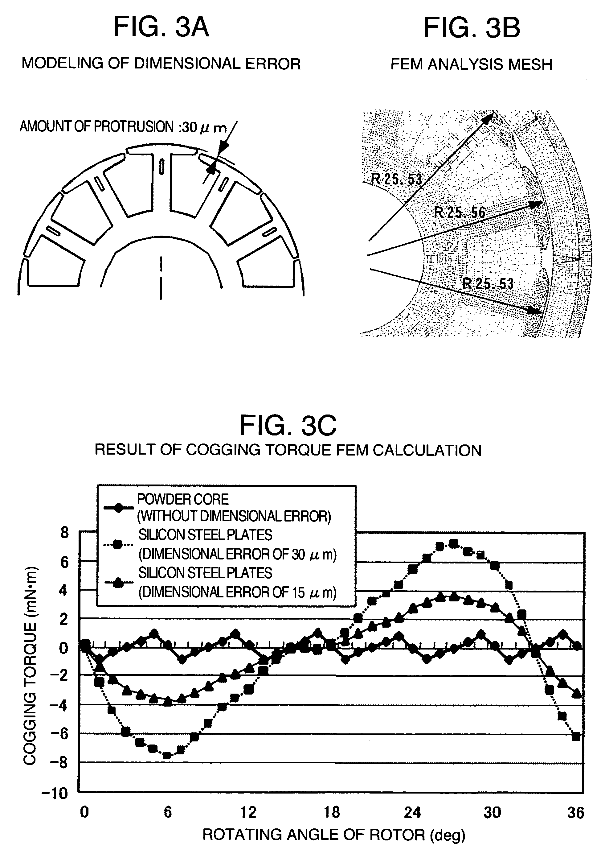
[0022]Specifically, the stator core is constituted using a powder core, which is highly compacted, in the entire stator or at least teeth. The powder core is made by compacting electrically insulated iron powder such that its density is equal to or higher than 7.5 g / cm3. As a result, errors in density are restrained to 5% or less in terms of the magnetization property in at least the teeth, and dimensional errors are restrained to 1 / 20 or less as long as a gap.

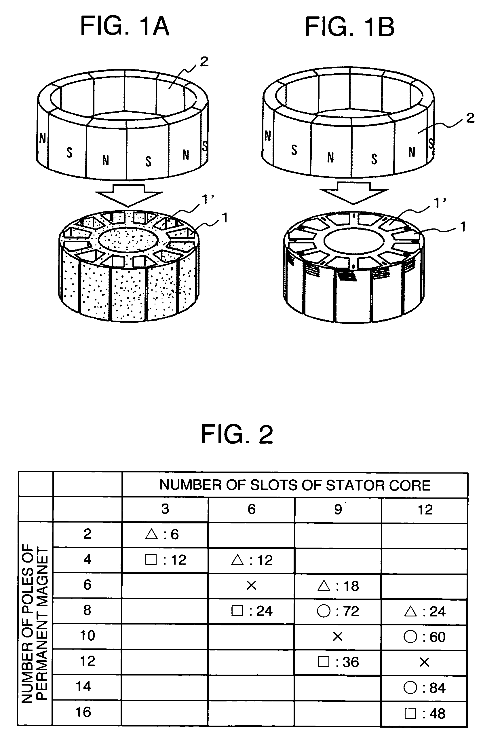
[0023]Also, a combination of the number of magnetic poles of the rotor with the number of slots of the stator sa...


PUM


Abstract

A three-phase permanent magnet brushless motor comprises a stator having three-phase windings, and a rotor having a permanent magnet with a plurality of poles for serving as a field magnet. The stator comprises a stator core which includes a powder core that is compacted at a high density in at least teeth thereof. A combination of the number of magnetic poles of the rotor with the number of slots of the stator satisfies a condition that a least common multiple of the number of slots and the number of magnetic poles is 60 or more in a region in which the number of magnetic poles is 16 or less, and the number of slots is 12 or less. The powder core is made by compacting magnetic powders to have a green density of 7.5 g / cm3 or higher.

Description

BACKGROUND OF THE INVENTION[0001]The present invention relates to a three-phase permanent magnet brushless motor, and more particularly, to the structure of a reduced cogging torque powder core permanent magnet motor which is less affected by variations associated with manufacturing.[0002]Permanent magnet brushless motors are used to drive machines for converting electric energy to mechanical power in industrial, home-electric, and automobile applications. Since importance is placed on a reduction in size of motors in addition to an improved efficiency, the reduction in size has been accomplished by an increase in density of coils in a stator core, resulting from the employment of high energy product magnets containing rare earth materials, a core division manufacturing method, and the like.[0003]However, since the permanent magnet brushless motor has a high energy product of the magnet, a pulsatile torque called a “cogging torque” is generated due to a relationship between the numb...

Claims


Application Information

Patent Timeline
Patent Type & Authority Patents(United States)
IPC IPC(8): H02K1/12
CPCH02K1/02H02K29/03H02K21/22
Inventor ENOMOTO, YUJITAKAHASHI, AKESHIITO, MOTOYAMASAKI, RYOSOYAMAZAKI, KATSUYUKIYAMAZAKI, MASAHIDEKITAMURA, MASASHIISHIHARA, CHIOASAKA, KAZUOOHIWA, SHOJIMOTEGI, YASUAKI
Owner JAPAN SERVO CO LTD
Why Eureka
Try Eureka