Method and apparatus for measuring scattering coefficient of device under test

a technology of scattering coefficient and measurement method, which is applied in the direction of measurement device, resistance/reactance/impedence, instruments, etc., can solve the problems of difficult to accurately remove the error increase the cost, and many errors of the measurement system, so as to reduce the overall size of the measuring apparatus and reduce the cost. , the effect of reducing the purity of the measurement signal

Active Publication Date: 2009-09-22
MURATA MFG CO LTD
View PDF8 Cites 7 Cited by
  • Summary
  • Abstract
  • Description
  • Claims
  • Application Information

AI Technical Summary

Benefits of technology

[0011]Accordingly, an object of preferred embodiments of the present invention is to provide a measuring method and measuring apparatus for vector-measuring a scattering coefficient of a device under test substantially using a scalar measuring instrument while enabling a reduction in the size of the measuring instrument and the cost.
[0017]The present invention reveals that a vector measured value (scattering coefficient) of a reflected wave and / or transmitted wave in a high frequency range can be substantially obtained by a scalar value measurement that is an inexpensive basic measurement virtually independent of frequency (electric power measurement using a power meter or a power sensor, voltage measurement using a voltmeter, current measurement using an ammeter). Here, a scalar measuring instrument performing a scalar measurement is a measuring instrument that measures only amplitude information (magnitude of amplitude) on electric power, voltage, or current. In the case of high-frequency devices, which are often produced by small-lot production of a wide variety of products, with an inexpensive measuring instrument according to the present invention, it is possible to prepare it for each device, and this can reduce the burden on a step, such as a changeover. The characteristics described above provide a considerable advantage to ensuring of the reproducibility of measurement in measurement in a high frequency range at or above the extremely high frequency band, which requires fine adjustment of a measurement system. The present invention can perform vector error correction while suppressing an increase in the price of a measurement system as long as electric power measurement, which is basically thermal measurement, is possible. A technique of the present invention is not multiplicative phase detection using a mixer or sampler but additive phase detection making use of a change in a measured value during load fluctuations. Therefore, essentially, there is no limit to the input bandwidth. Accordingly, there is a possibility that it can be extended to a frequency band of light.
[0018]In superimposing at least three vector signals on a reflected wave reflected from a DUT or a transmitted wave transmitted through the DUT, three states can be easily obtained by provision of at least three directional errors or leakage errors and directional error selector means or leakage error selector means that selects among those errors. It is not necessary to prepare a scalar measuring instrument for each of the states to obtain a measured value in the three states, and a single measuring instrument is sufficient. Accordingly, unlike a system that requires a large number of electric-power measuring instruments, as in Non-Patent Document 1 and Patent Document 1, the overall size of a measuring apparatus can be reduced, and the cost can also be reduced.
[0019]A reflection coefficient measurement system can be easily constructed by provision of a coupler (directional coupler) in a measurement signal path joining a signal source and a DUT, attachment of directional errors that can be switched among at least three states to a first port of another signal path joined to the measurement signal path by the coupler, and connection of a reflected-wave scalar measuring instrument to a second port thereof. A transmission coefficient measurement system can be easily constructed by connection of a signal path in which a DUT is present and a signal path in which leakage errors that can be switched among at least three states is present in parallel between a signal source and a transmitted-wave scalar measuring instrument. In addition, a one-path two-port measurement system can be constructed by combination of a reflection coefficient measurement system and a transmission coefficient measurement system. A full two-port measurement system and a full three-port measurement system can also be constructed by switching of a signal source using a switch. In this case, both scattering coefficients, i.e., a reflection coefficient and a transmission coefficient, can be measured at the same time by switching among directional errors and leakage errors using selector means while maintaining connection between the DUT and the measurement system.
[0021]As described above, according to the first embodiment of the present invention, at least three scalar value measurements corresponding to different states of a measurement system are performed in measurement of a reflected wave reflected from a DUT and / or a transmitted wave transmitted through the DUT, and a scattering coefficient is mathematically determined from three obtained scalar measured values. That is, a scattering coefficient of the reflected wave and / or transmitted wave in a high frequency range can be substantially obtained by a scalar value measurement that is an inexpensive basic measurement virtually independent of frequency. As a result, unlike a VNA, there is no problem in which the price significantly increases with an increase in a measured frequency, and an increase in frequency does not lead to a loss occurring in frequency conversion and a decrease in the purity of a measurement signal. The number of scalar measuring instruments can also be reduced, compared with a vector measurement technique using a known electric-power measuring instrument, so the overall size of a measuring apparatus and the cost can be reduced.
[0022]According to the second embodiment of the present invention, two vector signals are superimposed on a reflected wave reflected from a DUT and / or a transmitted wave transmitted through the DUT, superimposed signals are each measured as a scalar value by a scalar measuring instrument, and the two obtained scalar values are converted into two vector values using relation values of the two vector signals. A scattering coefficient of the DUT can be determined from one of the two converted vector values. Therefore, the number of times measurements are performed can be reduced, and thus the time required for the measurements can be shortened.

Problems solved by technology

When a wave reflected from or transmitted through a DUT is observed by a measurement system, ordinarily, it has many errors of the measurement system.
If only amplitude information (scalar value) for them is observed, it is difficult to accurately remove errors of the measurement system.
However, for the structure of the VNA, there is a problem of a considerable increase in cost caused by an increase in the number of stages of the local oscillator and mixer of the PLL with a rise of a measured frequency or by other reasons.
In addition, an increase in frequency leads to a loss occurring in frequency conversion and a decrease in the purity of a measurement signal, thus resulting in a problem in which a high-precision measurement is difficult.
However, it is necessary to measure four electric powers by four electric-power measuring instruments to measure reflection, so there is a problem in which the overall size of a measuring instrument is increased and the cost is also increased.
This causes a further increase in the overall size of a measuring instrument, and also raises the cost.Non-Patent Document 1: G. F. Engen, “The six-port reflectometer: An alternative network analyzer, “IEEE Transactions on Microwave Theory and Techniques, vol.

Method used


Image

  • Method and apparatus for measuring scattering coefficient of device under test
  • Method and apparatus for measuring scattering coefficient of device under test
  • Method and apparatus for measuring scattering coefficient of device under test

Examples


first preferred embodiment

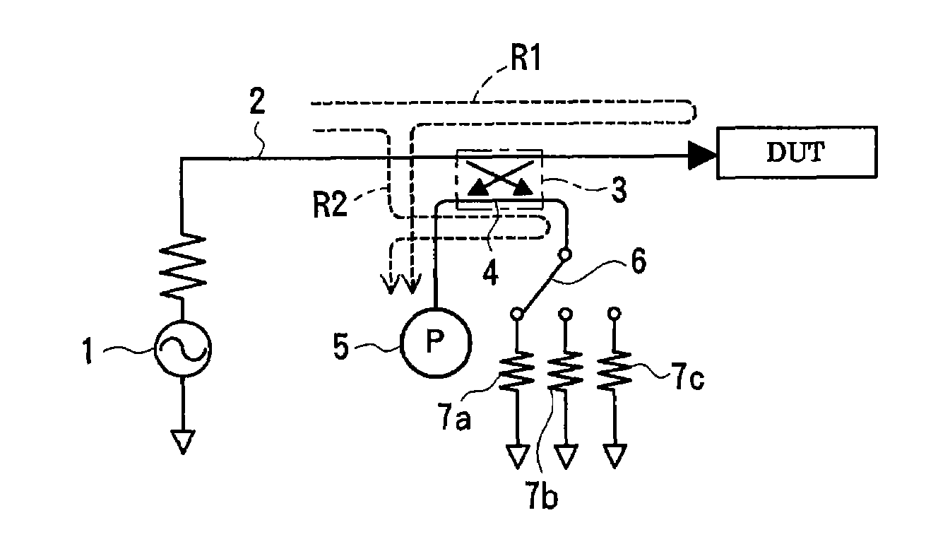
[0044]FIG. 1 illustrates an apparatus for measuring a reflection coefficient of a DUT according to a first preferred embodiment of the present invention. A signal generated by a signal source 1 including an oscillator passes through a measurement signal path 2 and is applied to a DUT. A coupler 3 separating part of signals passing through the measurement signal path 2 is disposed in the measurement signal path 2. A first port of an error signal path 4 coupled to the measurement signal path 2 by the coupler 3, the first port being adjacent to the signal source, is connected to an electric-power measuring instrument 5 measuring a reflected wave as a scalar value, such as a power meter. A second port of the error signal path 4, the second port being adjacent to the DUT, is connected to three kinds of directional errors 7a to 7c via a directional selector switch 6. The directional errors 7a to 7c have different reflection phases from each other, and relation values thereof (relative vec...

second preferred embodiment

[0067]FIG. 6 illustrates an apparatus for measuring a transmission coefficient of a DUT according to a second preferred embodiment of the present invention. Measurement signals generated by a signal source 1 are separated into a first measurement signal for a measurement signal path 9 and a second measurement signal for an error signal path 10 by a power splitter 8. The first measurement signal entering the measurement signal path 9 is applied to the DUT. The second measurement signal entering the error signal path 10 is applied to one of three leakage errors 12a to 12c via a leakage selector switch 11. A wave transmitted through the DUT and a wave transmitted through each of the leakage errors 12a to 12c are superimposed, and superimposed signals are each measured as an electric-power value (scalar value) by an electric-power measuring instrument 13. The leakage errors 12a to 12c have different phases of transmitted waves from each other, and relation values (relative vector values...

third preferred embodiment

[0076]FIG. 7 illustrates an example of a one-path two-port measurement system in which the reflection coefficient measurement system illustrated in FIG. 1 and the transmission coefficient measurement system illustrated in FIG. 6 are combined. Measurement signals are separated by a power splitter 8. A first measurement signal is applied to a DUT, and a second measurement signal is applied to one of three leakage errors 12a to 12c via a leakage selector switch 11. A superimposed signal of a wave transmitted through the DUT and a wave transmitted through each of the leakage errors 12a to 12c is measured as an electric-power value (scalar value) by an electric-power measuring instrument 13. A coupler 3 is disposed in a measurement signal path 2. A first port of a signal path coupled to the measurement signal path 2 by the coupler 3, the first port being adjacent to the signal source, is connected to an electric-power measuring instrument 5 measuring a reflected wave as an electric-power...


PUM


Abstract

A measuring method and measurement system that includes a signal source that applies a signal to a device under test, a scalar measuring instrument that measures a reflected wave reflected from the device under test or a transmitted wave transmitted through the device under test as a scalar value, and a superimposing signal system that superimposes three different vector signals whose relation values are specified in advance on the reflected wave or the transmitted wave of the device under test. The three vector signals are superimposed on the reflected wave or the transmitted wave of the device under test, and the superimposed signals are each measured as a scalar value by the electric-power measuring instrument. The three measured scalar values are converted into a single vector value using the specified relation values of the three vector signals, thereby obtaining a transmission coefficient of the device under test.

Description

CROSS REFERENCE TO RELATED APPLICATIONS[0001]The present application is a continuation of International Application No. PCT / JP2006 / 316465, filed Aug. 23, 2006, which claims priority to Japanese Patent Application No. JP2005-253158, filed Sep. 1, 2005, the entire contents of each of these applications being incorporated herein by reference in their entirety.FIELD OF THE INVENTION[0002]The present invention relates to a method and apparatus for vector-measuring a scattering coefficient of a device under test (DUT), such as an electronic device.BACKGROUND OF THE INVENTION[0003]The operating frequency of high-frequency electronic circuits is increasing more and more, so it is necessary to accurately measure electric characteristics of an electronic device used in such a circuit in a high frequency range. Among items to be measured at high frequencies, a reflection coefficient and a transmission coefficient are important. A reflection coefficient is the ratio of a wave reflected from a D...

Claims


Application Information

Patent Timeline
Patent Type & Authority Patents(United States)
IPC IPC(8): G01R27/04G01R27/28G01R27/32
CPCG01R27/28G01R27/04G01R27/06
Inventor MORI, TAISHIKAMITANI, GAKU
Owner MURATA MFG CO LTD
Why Eureka
Try Eureka