
Method and device for processing optical signals in computer mouse

a technology of optical signals and computer mouse, which is applied in the field of electric digital data processing, can solve the problems of low precision and vulnerability, now hardly found on the market, and wrong positioning

Inactive Publication Date: 2009-09-29
SHENZHEN GOZLAB CO LTD
View PDF9 Cites 2 Cited by
  • Summary
  • Abstract
  • Description
  • Claims
  • Application Information

AI Technical Summary

Benefits of technology

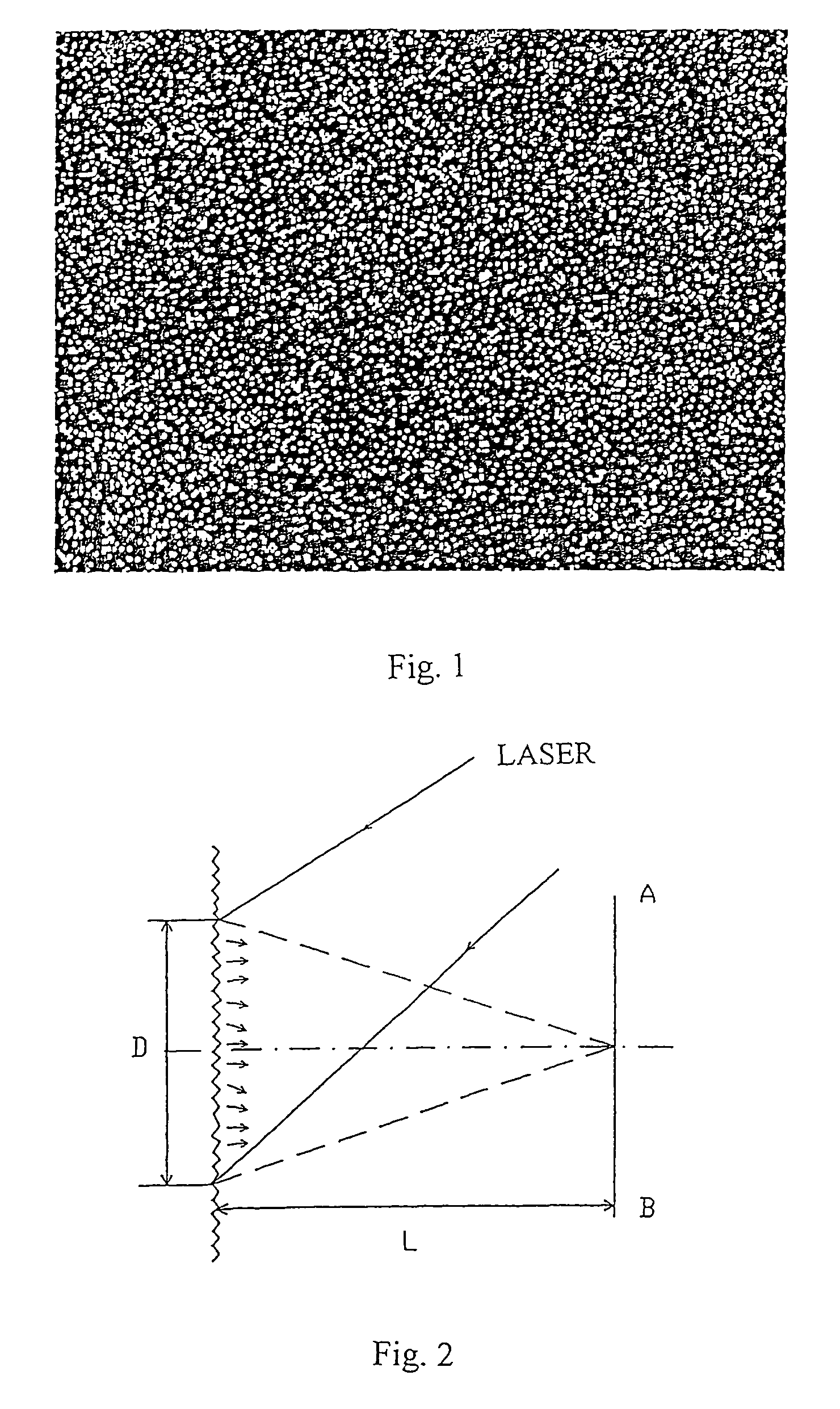
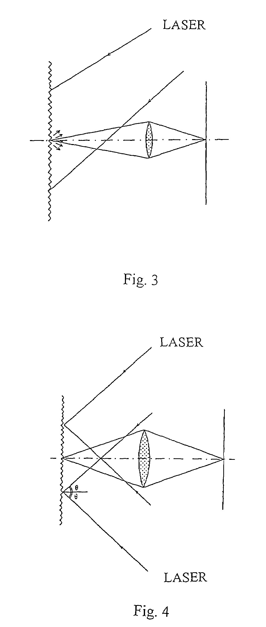
"The present invention provides a method and device for processing optical signals in a computer mouse using laser speckle signals. This technology solves the problem of inconvenience in using previous methods and devices, which were complex and costly. The method is simple and cost-effective, and can provide high-precision and long-service life for the computer mouse."

Problems solved by technology

Because this type of mouse is of a purely mechanical structure, it has the inherited disadvantages of low precision and vulnerability, and it is now hardly found on the market.
However, as the basic positioning mechanism of this type of mouse is still the mechanical rotary ball, just like the conventional mechanical mouse, it will cause the cursor to move slowly or jump resulting in wrong positioning.
This is mainly due to the dust attached on the inside rotary shafts.
As this type of photo mouse has to be operated on a special mouse pad which needs to be always clean, it is not convenient to use the mouse.
Therefore, it has not been popularized widely.
However, due to the complicated principle and structure, its cost remains high, and due to the limitation of the technological and cost factors, its reacting speed is not sufficient.

Method used


Image

  • Method and device for processing optical signals in computer mouse
  • Method and device for processing optical signals in computer mouse
  • Method and device for processing optical signals in computer mouse

Examples


embodiment 1

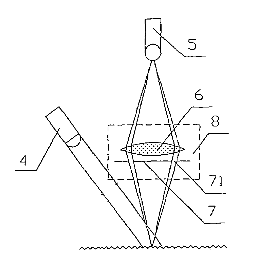
[0046]In FIG. 5 and FIG. 6, the device according to the present invention includes a mouse body, and as shown in FIG. 5 and FIG. 6, inside the mouse body, an amplifying and shaping module 1, a direction identifying and counting module 2, and a computer interface circuit 3 are disposed and connected in sequence, and the device further includes a laser device 4 and a photo sensor 5 for receiving laser speckle signals from the object surface illuminated by laser beams. Said photo sensor 5 transfers the received photoelectric signals to the amplifying and shaping module 1.

[0047]Said photo sensor 5 has groups of photoelectric sensing units, wherein each group consists of two or more photoelectric sensing units aligned in a line. After laser speckle signals or laser speckle interference signals from the object surface illuminated by laser beams are received, relevant photoelectric signals are amplified and shaped by the group of photoelectric sensing units, so as to calculate the size of ...

embodiment 2

[0049]As shown in FIG. 7 and with reference to FIG. 6, the difference between the present embodiment and embodiment 1 is that, in the present embodiment, a focusing lens 6 is arranged in the light path for receiving laser speckle signals in the photo sensor 5. As the structure, principle and operation method are the same as those of the embodiment 1, unnecessary details will not be given here.

embodiment 3

[0050]As shown in FIG. 8 and with reference to FIG. 6, the difference between the present embodiment and embodiment 1 is that, in the present embodiment, a beam splitter 8 is arranged in the light path, and the laser beam emitted by the laser device is split into two or more beams by the beam splitter 8 to illuminate onto one or more areas of the surface producing laser speckle interferences, wherein each area illuminated by at least two beams.

[0051]Here, the beam splitter 8 consists of a focusing lens 6 and a pupil 7, wherein said pupil 7 has at least three light apertures 71 arranged in front of or behind the focusing lens 6. The centers of the light apertures 71 are not in a line. Since the centers of the light apertures 71 are not in a line, two-dimensional sampling of photoelectric signals of displacement may be conducted. FIG. 8 shows only two light apertures in one dimension, and the light aperture in the other dimension which is not shown is similar in structure. In the pres...


PUM


Abstract

The present invention discloses a method and a device for processing optical signals in a computer mouse, which is related to electric digital data processing. The method is that the relative displacement vector between the mouse device and the illuminated object surface producing laser speckles is reflected by means of collecting movement information of laser speckle signals. The device for carrying out the method consists of a mouse body; inside said mouse body, an amplifying and shaping module, a direction identifying and counting module and a computer interface circuit for processing photoelectric signals are disposed and connected in sequence, characterized in that, said device further includes at least one laser device and a photo sensor for receiving laser speckle signals from the object surface illuminated by laser beams. Said photo sensor transfers the received photoelectric signals to the amplifying and shaping module. This invention has a simple structure, high technical feasibility and high precision.

Description

TECHNICAL FIELD[0001]The present invention relates to electric digital data processing, and more particularly, to a method and a device for processing optical signals in a computer mouse.BACKGROUND ART[0002]Since computer mouse came into being at the end of 1968, the following four generations, which are divided from a technical view point, have been developed,[0003](1) Mechanical Mouse:[0004]The operation principle of the mechanical mouse lies in the use of the rotary ball at the bottom of the mouse, i.e. when the rotary ball physically contacts the surface of the table and rotates to different directions, it drives the pressure rotary shafts in different directions to rotate. These rotary shafts are connected to a circular coder on which contacts are arranged in a circle. The rotation of the rotary ball is transferred through pressure shafts to enable the contacts to be in contact with contact strips so as to produce on-off signals which are further transformed into 0-1 signals. T...

Claims


Application Information

Patent Timeline
Patent Type & Authority Patents(United States)
IPC IPC(8): G06F3/033G06F3/03
CPCG06F3/0317G06F3/0354
Inventor ZHANG, HONG-ZHI
Owner SHENZHEN GOZLAB CO LTD
Learn More