Mixing element for an exhaust gas system

a technology of mixing element and exhaust gas, which is applied in the direction of electric control, machines/engines, transportation and packaging, etc., can solve the problems of comparatively high installation and analyzer circuit cost, and achieve the effect of less expensiv

Active Publication Date: 2009-10-06
PUREM GMBH
View PDF18 Cites 11 Cited by
  • Summary
  • Abstract
  • Description
  • Claims
  • Application Information

AI Technical Summary

Benefits of technology

[0004]This invention is concerned with the problem of providing in a dual-flow exhaust gas system, the function monitoring of catalytic converter arrangements in exhaust lines less expensively.
[0005]This invention is based on the general idea of providing a mixing element for a dual-flow exhaust gas system, where this mixing element can be used in the two exhaust lines of a dual-flow exhaust gas system through two inlet openings and two outlet openings, whereby the four openings mentioned above are interconnected in the mixing element in such a way that each inlet opening is connected to two outlet openings. The exhaust gases entering the mixing element through the one inlet opening thus emerge from the mixing element through both outlet openings. Likewise, the exhaust gases entering the mixing element through the other inlet opening also emerge from the mixing element through both outlet openings. For the dual-flow exhaust gas system equipped with this mixing element, the exhaust gases carried through the one exhaust line to the mixing element flow in both exhaust lines downstream from the mixing element. Similarly, this is true for the other exhaust line, whose exhaust gases, when supplied to the mixing element, flow in both exhaust lines downstream from the mixing element. The use of such a mixing element thus results in a gas mixture emerging from both outlet openings downstream from the mixing element such that this gas mixture is formed from the two individual gas streams that are sent separately to the two inlet openings. As a result, a portion of the exhaust gases of the one exhaust line as well as a portion of the exhaust gases of the other exhaust line flow in both exhaust lines downstream from the mixing element. A sensor mounted downstream from the mixing element can thus analyze the exhaust gases of both exhaust lines running upstream from the mixing element. A malfunction in one or the other or in both catalytic converter arrangements of the two exhaust lines can thus be detected with the help of only a single sensor. Accordingly, this makes it possible to reduce the manufacturing cost for a dual-flow exhaust system.
[0006]According to an embodiment, the mixing element contains a channel system connecting each inlet opening to the two outlet openings via two separate channels. In this way, a predetermined mixing ratio can be achieved between the two exhaust gas streams supplied in the two exhaust gas streams that are discharged. In addition, the flow resistance of the mixing element can be reduced with such a channel system.

Problems solved by technology

Such probes or sensors are comparatively expensive, however, in particular the associated expense for installation and for the analyzer circuits.

Method used


Image

  • Mixing element for an exhaust gas system
  • Mixing element for an exhaust gas system
  • Mixing element for an exhaust gas system

Examples


Embodiment Construction

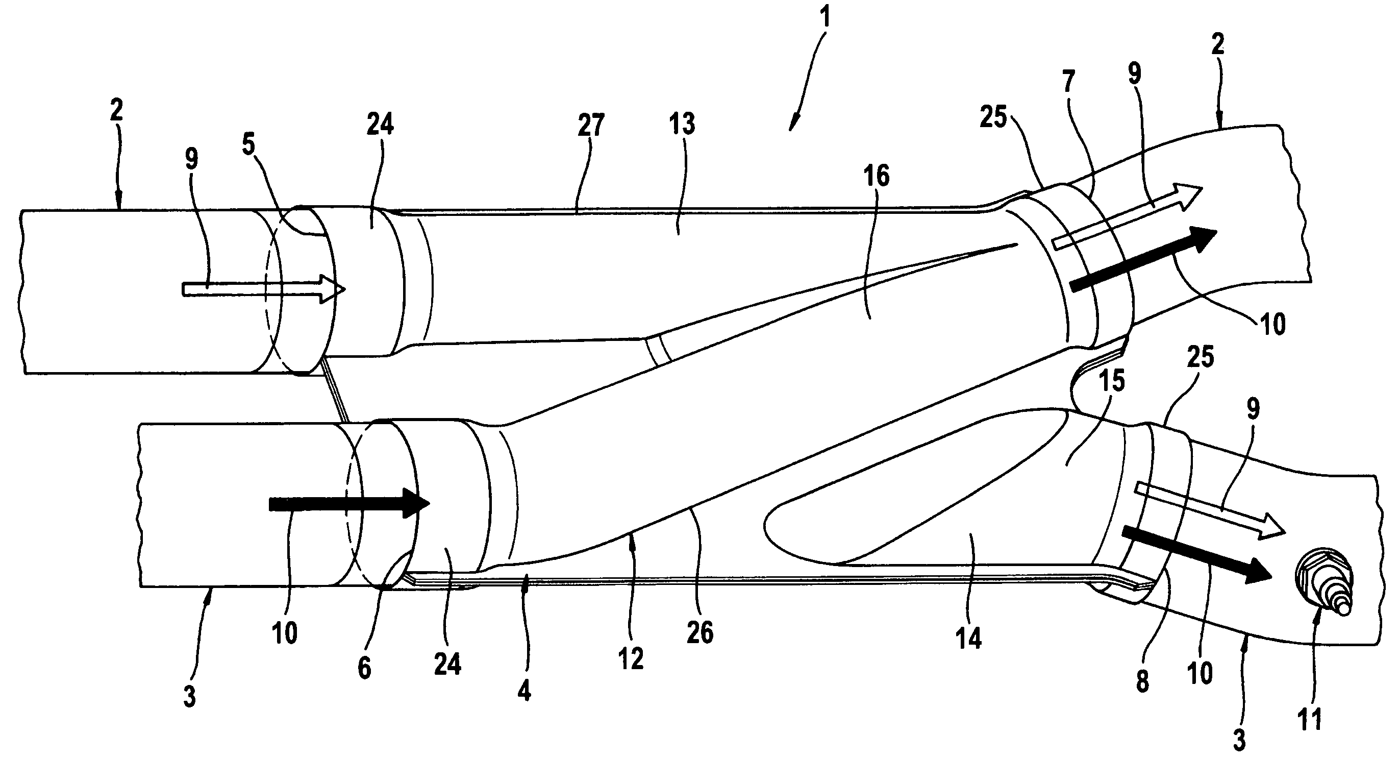
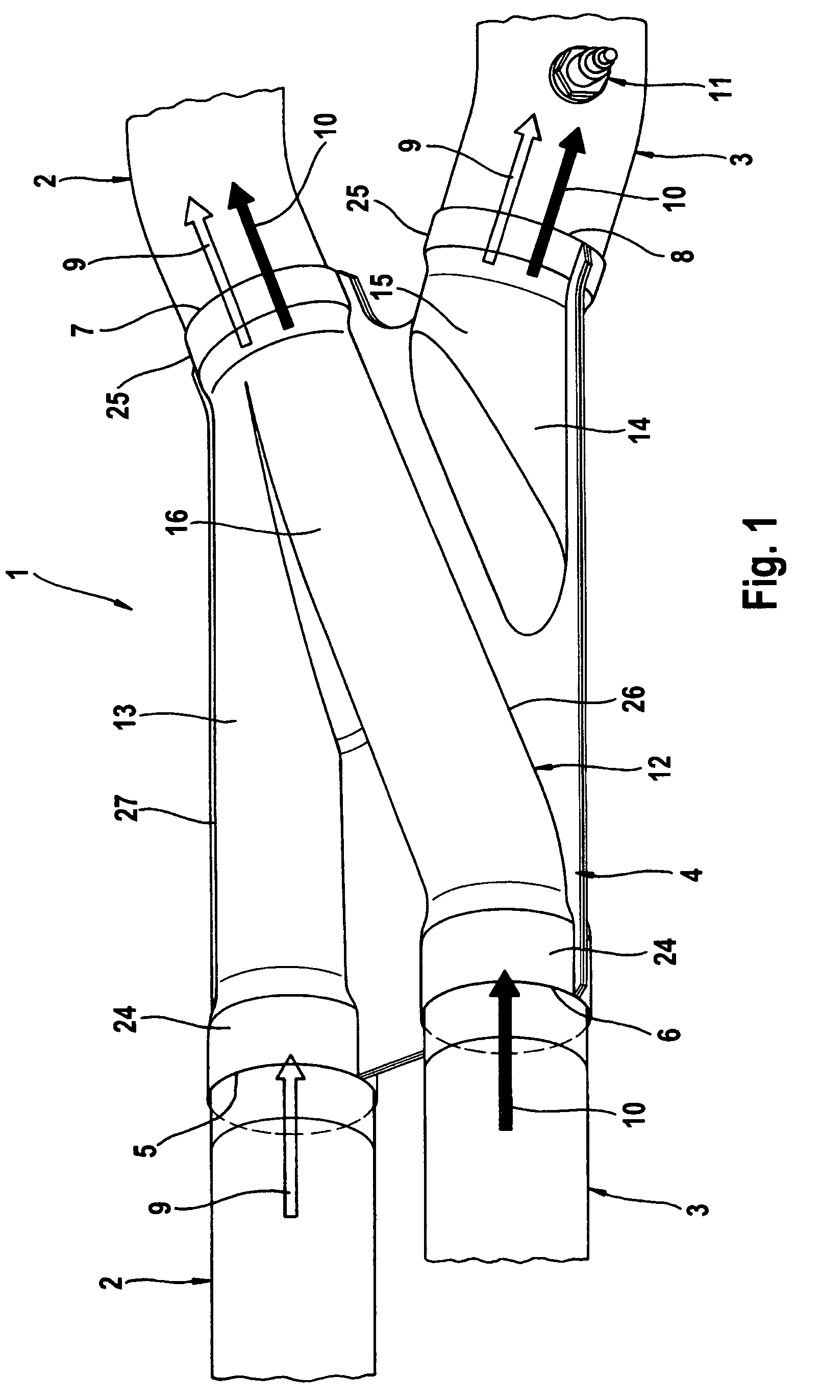
[0014]According to FIG. 1, a dual-flow exhaust gas system 1 has two exhaust lines 2, 3 which carry exhaust gases away from an internal combustion engine (not shown) such as the type installed in a motor vehicle. The two exhaust lines 2, 3 are linked together by a mixing element 4. The two exhaust lines 2, 3 lead separately to the mixing element 4 and also lead separately away from the mixing element 4. Accordingly, the mixing element 4 has two inlet openings, namely a first inlet opening 5 assigned to the first exhaust line 2 and a second inlet opening 6 assigned to the second exhaust line 3. In addition, two outlet openings are also provided, namely a first outlet opening 7 assigned to the first exhaust line 2 and a second outlet opening 8 assigned to the second exhaust line 3. This mixing element 4 is adapted so that each of the inlet openings 5, 6 communicate with both outlet openings 7, 8. As a result, a first exhaust gas stream 9, which is supplied through the first exhaust lin...


PUM

PropertyMeasurementUnit
sizeaaaaaaaaaa
exhaust temperaturesaaaaaaaaaa
mixing ratioaaaaaaaaaa

Abstract

The present invention relates to a mixing element and an exhaust system of an internal combustion engine. The mixing element has two inlet openings and two outlet openings, wherein each inlet opening communicates with both outlet openings.

Description

FIELD OF THE INVENTION[0001]The present invention relates to a mixing element for an exhaust gas system of an internal combustion engine. The invention also relates to an exhaust gas system equipped with such a mixing element.BACKGROUND OF THE INVENTION[0002]Exhaust gas systems of internal combustion engines may be designed as dual flow, i.e., having two separate exhaust gas lines carrying the exhaust gases away from the internal combustion engine in parallel. For example, dual-flow exhaust gas systems are expedient with V-type engines to remove the exhaust gases from the two cylinder banks separately. In addition, to reduce emissions of pollutants, it is customary to provide the exhaust system with exhaust gas purification devices such as catalytic converters and particulate filters. To check proper functioning of such exhaust gas treatment devices, a corresponding sensor and / or a corresponding probe can be provided in the exhaust line downstream from the respective device. With th...

Claims


Application Information

Patent Timeline
Patent Type & Authority Patents(United States)
IPC IPC(8): F01N3/00B01F23/10F01N13/08F01N13/18
CPCB01F3/02F01N3/2066F01N3/2892F01N13/08F01N13/1872F01N13/1894F02D41/1439B01F5/0641Y02T10/24F01N2240/20F01N2470/14F01N2470/16F01N2560/02F01N2560/021F01N2610/02F02D2041/1468Y02A50/20Y02T10/12B01F23/10B01F25/4321
Inventor MUELLER, MANFREDKOBE, JUERGENBRAUN, JOACHIM
Owner PUREM GMBH
Why Eureka
Try Eureka