Pipette guide

a pipette and guide technology, applied in the field of pipette guides, can solve the problems of primarily occurring errors, affecting so as to facilitate multi-directional loading of wells, reduce the risk of touching the aperture, and improve the accuracy of sample delivery

Inactive Publication Date: 2009-10-06
IBI SCI
View PDF17 Cites 36 Cited by
  • Summary
  • Abstract
  • Description
  • Claims
  • Application Information

AI Technical Summary

Benefits of technology

[0013]The aforesaid and other objectives are realized by providing a pipette guide and method of use as described herein. The pipette guide includes reference characters which identify the column of wells exposed by the slide plate. The rods of the device are manipulated to correspond with using either a 96 or 384 well plate. Upon setting the rods for the appropriate well plate, the corresponding reference characters are displayed and the proper notches are engaged with the slide plate and isolator, thereby allowing the guide to precisely “click in” at desired positions on the well plate. The invention also facilitates multi-directional loading of wells by providing access to the wells through an angled slot on the sliding plate. Another improvement in the invention is a slide plate which is thinner on the outer edges than the inner portion. The multi-thickness slide plate improves the precision in delivering a sample, while still allowing sliding motion between the well plate, cover and slide. Another improvement of the invention is the single well isolator which provides access to the reservoir through a biased, open-ended aperture that adequately guides the pipette tip but reduces the risk of touching the aperture. Finally, a novel selection assembly is presented which allows the user to easily and precisely choose the type of plate which is to be used.

Problems solved by technology

However, even skilled operators become distracted, confused or careless and make mistakes.
Errors primarily arise when a sample is introduced into the wrong well, or column or row of wells, or when the incorrect volume of sample is introduced.
The possibility of operator error in using well plates is known.
Specifically, the conventional pipetting guide does not allow the operator to readily identify the column of wells which are exposed for manipulation, the isolator port and slot are cumbersome, there is a gap between the slide plate and wells which could facilitate incorrect pipetting or contamination, and the mechanism for setting the plate type (96 versus 384 well) on the lateral slide rod is easily set incorrectly.

Method used


Image

  • Pipette guide
  • Pipette guide
  • Pipette guide

Examples


Embodiment Construction

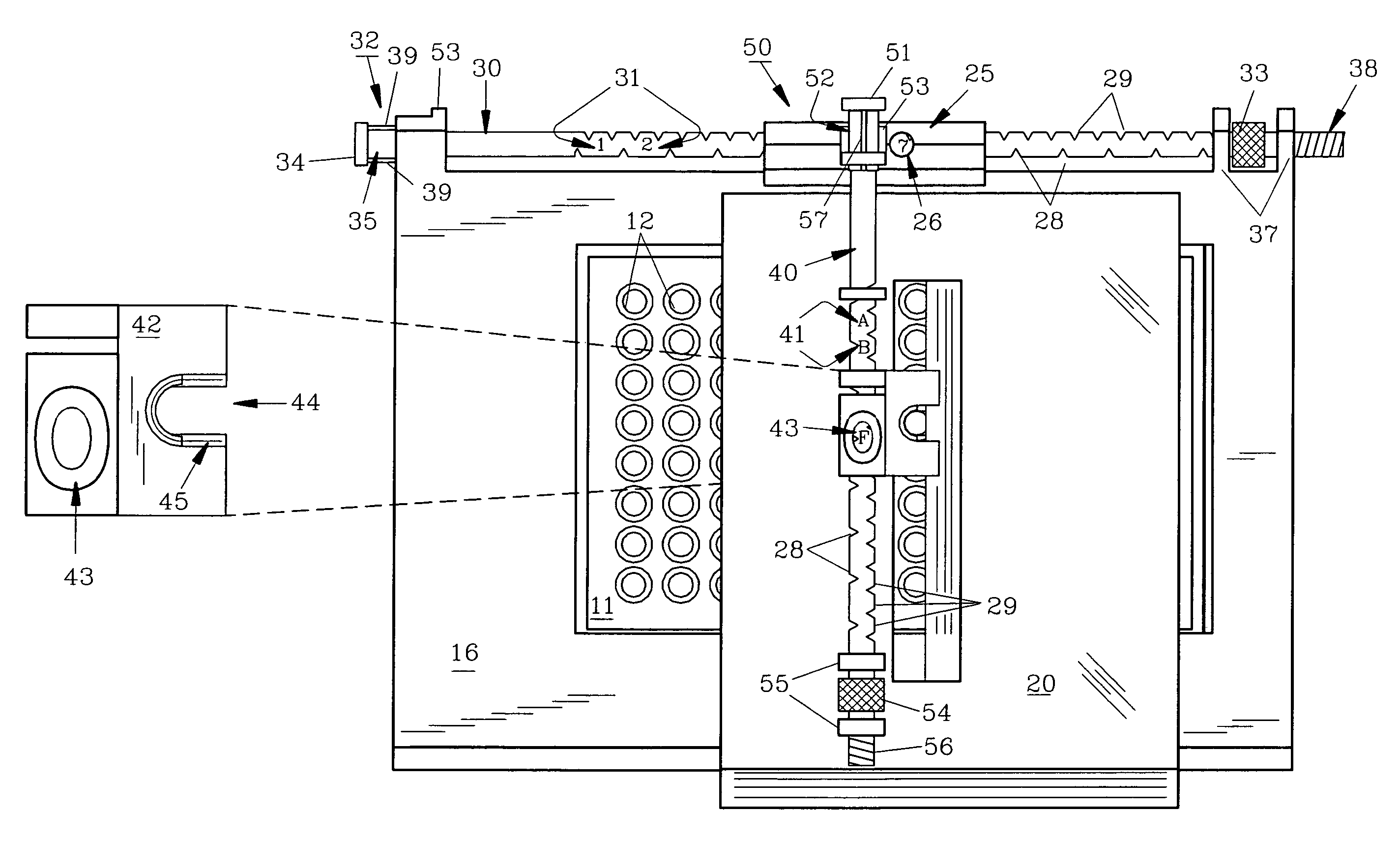
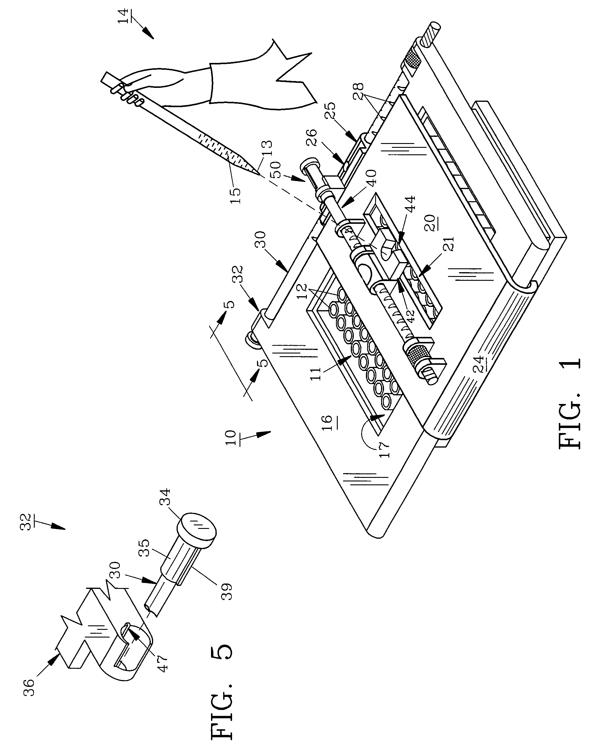
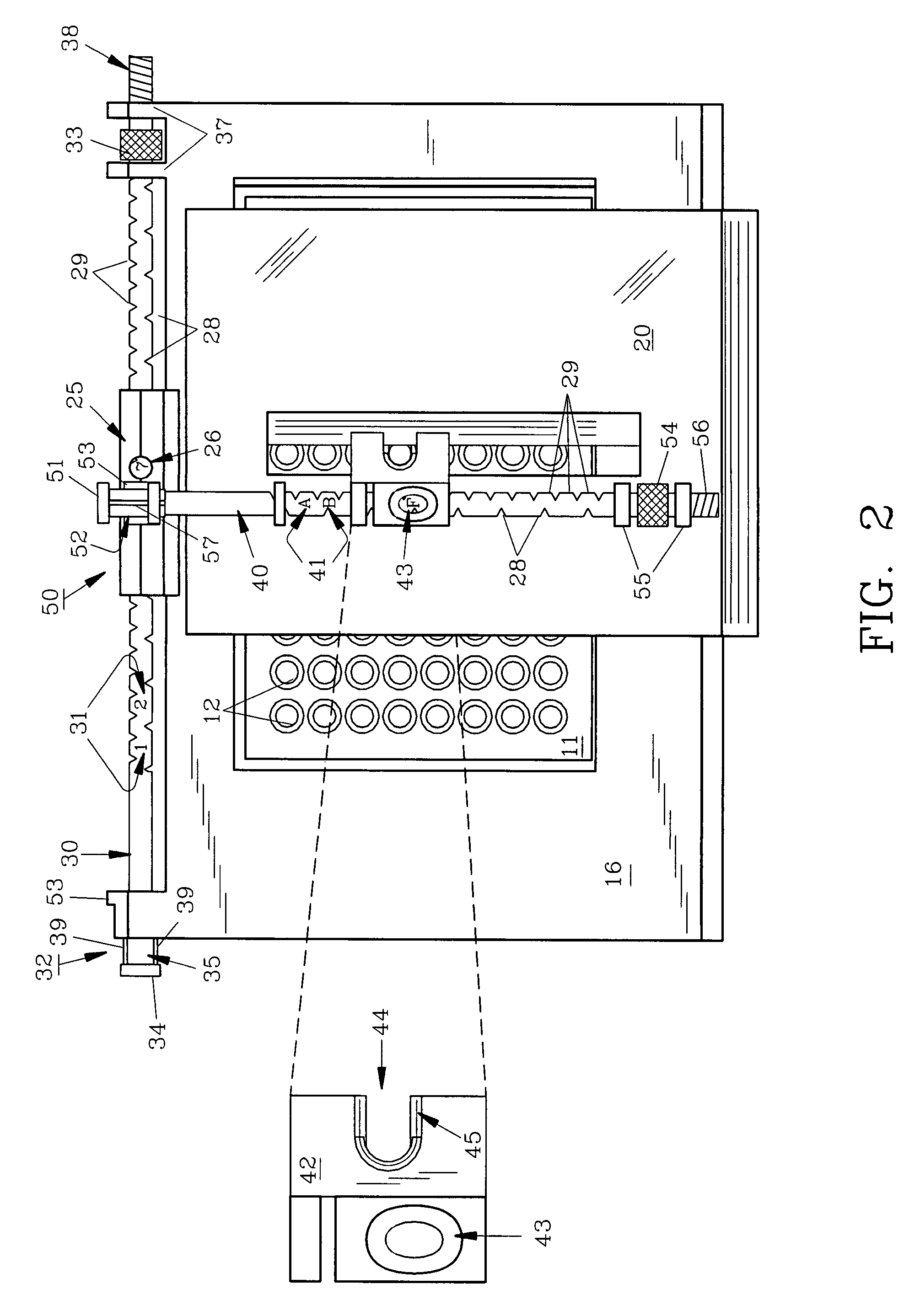
[0020]The major structural components of preferred pipette guide 10 include: cover 16 which fits over microtiter plate 11, slide 20 which defines angled slot 21, side rod 30 and lateral slide rod 40 with isolator 42, all shown in FIG. 1. Side rod 30 and lateral slide rod 40 are attached to cover 16 and slide 20 respectively (FIG. 2). Preferred components constituting the pipette guide improvement include: angled slot 21 (FIG. 3), thick portion 22 and thin portion 23 (FIG. 4), and column reference characters 31, flange aperture 26, isolator port 44, side rod adjuster 32 and lateral slide rod adjuster 50 as seen in FIG. 2.

[0021]Thick portions 22 as seen in FIG. 4 comprise opposing rimmed edges 22 on the bottom surface of slide 20 at the perimeter of slot 21 with acutely angled side wall 46 and obtusely angled side wall 48. As further seen in FIG. 4, opposing rimmed edges 22 define a slope with respect to the plane of slide 20. The acutely angled side wall 46 is truncated to provide a ...


PUM


Abstract

A pipette guide for a standard well plate provides improvements over conventional guides. The improvements include: reference characters to signify a columns of wells exposed, an aperture for viewing those characters, a angled slot and open ended isolator for improved ergonomic function and visibility, a multilevel slide to help prevent contamination and a bi-directional selection assembly for selecting a 96 or 384 well plate.

Description

FIELD OF THE INVENTION[0001]The invention herein pertains to a laboratory device for precisely transferring liquids into standard well plates using conventional single or multichannel manual or electronic pipettes.DESCRIPTION OF THE PRIOR ART AND OBJECTIVES OF THE INVENTION[0002]Well plates or microtiter plates have taken the place of test tubes in many laboratories. Well plates are relatively inexpensive, require comparatively small sample sizes, are easy to dispose of, come in standard sizes and materials, and save precious laboratory time and resources by allowing simultaneous analysis of multiple samples. Due to their widespread use, many standard protocols are specifically designed to be performed in well plates. In addition, there are many devices which facilitate the use of well plates, such as pipettes, in particular multi-channel pipettes, reagent reservoirs, plate readers and plate reader data analysis programs.[0003]Laboratory personnel must be properly trained in well pl...

Claims


Application Information

Patent Timeline
Patent Type & Authority Patents(United States)
IPC IPC(8): B01L3/02
CPCB01L9/50B01L9/54B01L99/00B01L2300/0829B01L2200/087B01L9/56B01L2300/045B01L2300/046
Inventor REYNOLDS, CEDRIC S.
Owner IBI SCI
Why Eureka
Try Eureka