Surface treatment apparatus and method

a surface treatment and apparatus technology, applied in the direction of shaping tools, manufacturing tools, shape safety devices, etc., can solve the problems of high cycle fatigue, stress related failure, and component service life, and achieve the effect of reducing the overall processing time of the surface treatment operation and controlling the compressive residual stress

Active Publication Date: 2009-10-13
SURFACE TECH HLDG
View PDF14 Cites 37 Cited by
  • Summary
  • Abstract
  • Description
  • Claims
  • Application Information

AI Technical Summary

Benefits of technology

[0019]One advantage of the present invention is the ability to measure the dimensions of a workpiece in real time during a surface treatment operation. This eliminates the need to perform separate measurement steps before and / or after the surface treatment operation and thereby decreases overall processing time for the surface treatment operation.
[0020]Another advantage of the present invention is the ability to adjust surface treatment processing parameters in real time based upon the measured dimensions of the workpiece. This permits the desired depth and magnitude of compressive residual stress to be induced in the workpiece by adjusting the surface treatment processing parameters relative to the measured dimensions of the workpiece during processing.
[0021]Another advantage of the present invention is the ability to control the compressive residual stress induced in the workpiece by monitoring the depth of impingement of surface treatment elements rather than the force with which the surface treatment elements are impinged.
[0022]Another advantage of the present invention is the ability to measure the dimensions of a workpiece in real time during a surface treatment operation as a quality control measure. Dimensional variations beyond specified tolerances are identified and appropriate measures taken to either remedy the variation or else discard the workpiece.

Problems solved by technology

The high vibratory and tensile stresses experienced by rotating turbo machinery in operation, particularly the blading members of the fan, compressor, and turbine stages in gas turbine engines, make such components susceptible to high cycle fatigue (HCF) and other stress related failure mechanisms such as stress corrosion cracking (SCC).
HCF and SCC ultimately limit the service life of these components as prolonged exposure to such extreme operating conditions leads to the development of fatigue cracks in areas of the component subject to high operational stresses.
The fatigue life of a component is further limited by the occurrence of foreign object damage (FOD).
FOD, especially along the leading and trailing edges of blading members, significantly reduces the service life of aerospace components.
Compressive residual stresses are commonly introduced in critical areas of the component that are subject to high operational stresses and / or damage and are therefore prone to fatigue failure.
Despite being well known in the art, such methods of inducing compressive residual stress can be difficult to implement, particularly with respect to vanes and blading members used in gas turbine engines.
The difficulty lies not with the method of inducing the compressive residual stresses, but is instead related to the dimensional variations encountered within a single component as well as variations between individual components.
Variations in the thickness of a blade or vane, regardless of the source, can adversely impact the benefit of compressive residual stresses induced in the blade.
Where variations in thickness are present, the surface treatment process parameters selected may be inadequate to produce the designed residual stress distribution.
Alternatively, if the component is thinner than anticipated, the amount of material in the treated area may not be sufficient to accommodate or compensate for reacting tensile stresses that accompany the introduction of compressive residual stress leading to buckling or distortion in the component.
While this method is effective, it has one significant disadvantage: the act of measuring prior to treatment adds an additional step to the surface treatment process that may as much as double the surface treatment process time.
Another problem associated with the introduction of compressive residual stress involves the ability to precisely control the applied stress or force of the surface treatment process so as to obtain the desired compressive residual stress.
However, it may be difficult to obtain the necessary precision over the applied stress to accurately control the induced compressive residual stress.

Method used


Image

  • Surface treatment apparatus and method
  • Surface treatment apparatus and method
  • Surface treatment apparatus and method

Examples


Embodiment Construction

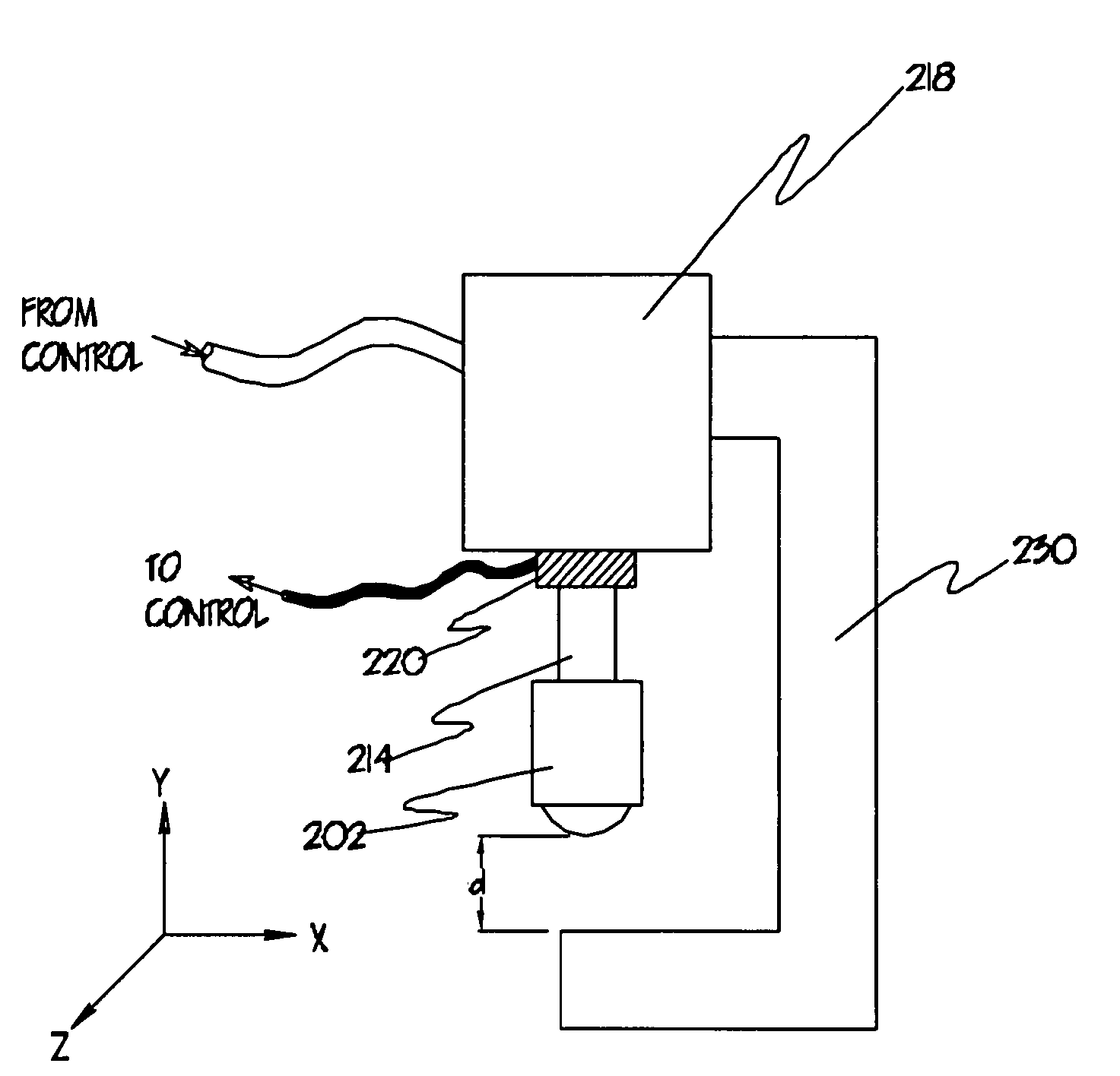
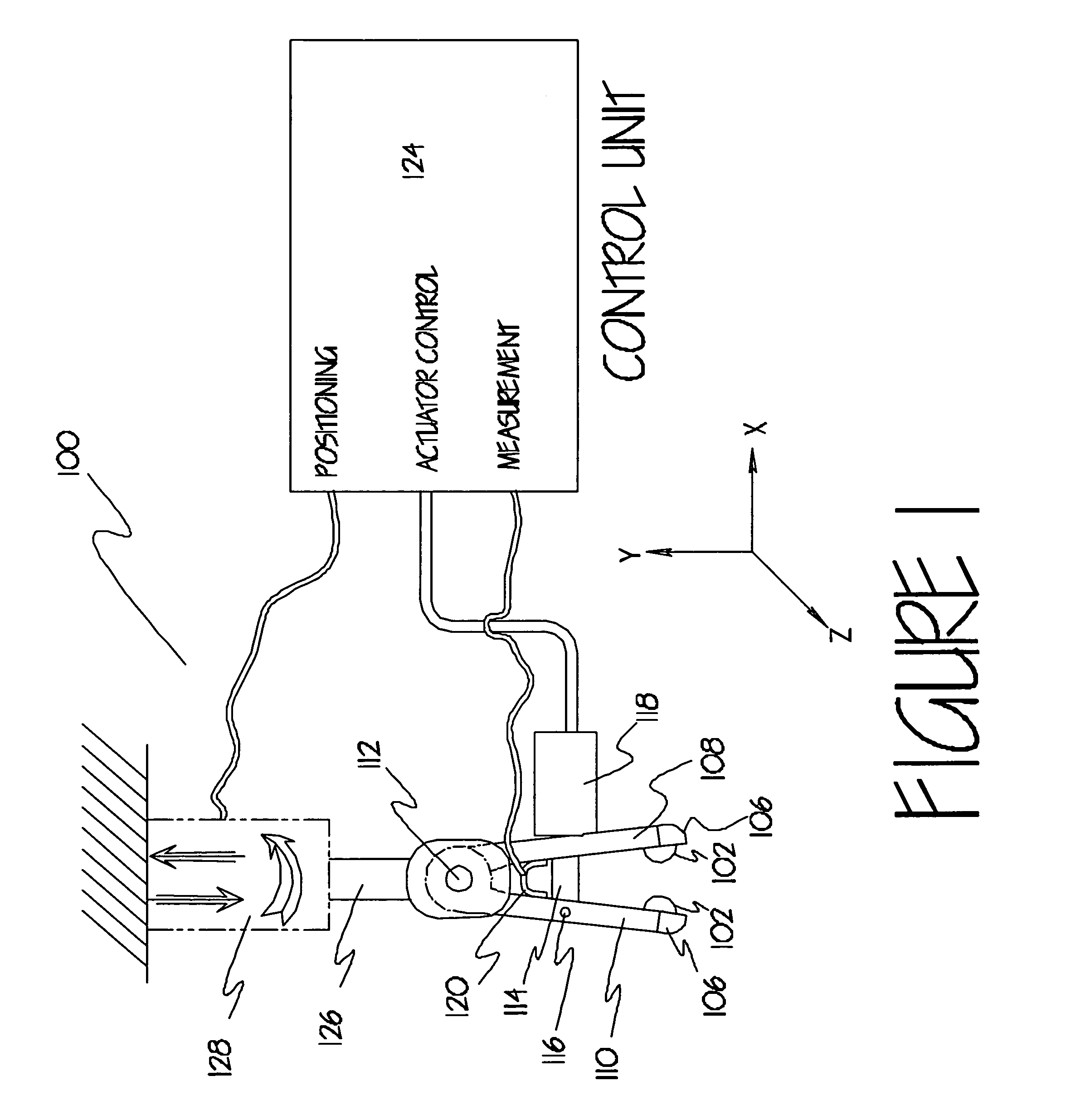
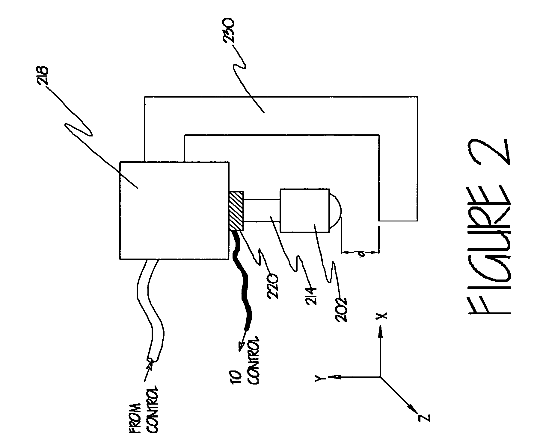
[0031]Referring to the embodiment of the present invention shown in FIG. 1, the apparatus 100 is comprised of surface treatment elements 102 for inducing compressive residual stress in the surface of a workpiece disposed within the tip portions 106 of a first arm 108 and a second arm 110. The first arm 108 and second arm 110 are oriented in a caliper-configuration such that the surface treatment elements 102 are in direct opposition to one another. The first arm 108 and second arm 110 are disposed within a base 126 for attaching the apparatus to a positioning device 128 such that the first arm 108 and second arm 110 are free to rotate relative to the base 126. A linkage 114 extends freely through the first arm 108 and terminates at a pivoting pin connection 116 in the second arm 110 thereby mechanically linking the first arm 108 to the second arm 110. An actuator 118 attached to the first arm 108 actuates the linkage 114 thereby moving the first arm 108 and second arm 110 in proximi...


PUM

PropertyMeasurementUnit
compressive residual stress distributionaaaaaaaaaa
compressive residual stressaaaaaaaaaa
displacementaaaaaaaaaa

Abstract

The present invention relates to a surface treatment apparatus and method for inducing compressive residual stress in the surface of a workpiece with dimensional variations. The method comprises the acts of measuring the dimensions of the workpiece during a surface treatment operation and adjusting the surface treatment process parameters to account for the measured dimensions. In one embodiment, the apparatus comprises two surface treatment elements oriented in opposition to one another in a caliper configuration. The surface treatment elements are positioned and impinged against the surface of a workpiece by an actuator controlled by a computer control unit. The depth to which the surface treatment elements are impinged is precisely controlled to achieve the desired magnitude and depth of compressive residual stress. A sensor operatively connected to the apparatus senses and relays the dimensions of the workpiece to a computer control unit that adjusts the operating parameters accordingly.

Description

BACKGROUND OF THE INVENTION[0001]This invention relates to a surface treatment apparatus and, more particularly, to an apparatus for inducing compressive residual stresses whereby the apparatus is capable of sensing variations in workpiece thickness and adjusting the applied surface treatment process parameters, such as the depth to which surface treatment elements are impinged, in response to such variations so that the desired depth and magnitude of compressive residual stress is induced in the surface of a workpiece. The invention also relates to a method of performing surface treatments whereby variations in workpiece dimensions are accounted for during the surface treatment process.[0002]The high vibratory and tensile stresses experienced by rotating turbo machinery in operation, particularly the blading members of the fan, compressor, and turbine stages in gas turbine engines, make such components susceptible to high cycle fatigue (HCF) and other stress related failure mechani...

Claims


Application Information

Patent Timeline
Patent Type & Authority Patents(United States)
IPC IPC(8): B21D17/04
CPCB23P9/00B23P9/02B23P9/04C21D7/06C21D7/08C21D7/04C21D2221/00
Inventor PREVEY, III, PAUL S.
Owner SURFACE TECH HLDG
Why Eureka
Try Eureka