Nailing machine and magazine

a nailing machine and magazine technology, applied in the field of nailing machines, can solve the problems of inability to adopt the above-described idle striking preventing mechanism, the nail head becomes inconspicuous after the nailing, etc., and achieve the effect of preventing idle striking

a nailing machine and magazine technology, applied in the field of nailing machines, can solve the problems of inability to adopt the above-described idle striking preventing mechanism, the nail head becomes inconspicuous after the nailing, etc., and achieve the effect of preventing idle striking

US7600661B2Inactive Publication Date: 2009-10-13MAX CO LTD

Image

  • Nailing machine and magazine
  • Nailing machine and magazine
  • Nailing machine and magazine

Examples


Embodiment Construction

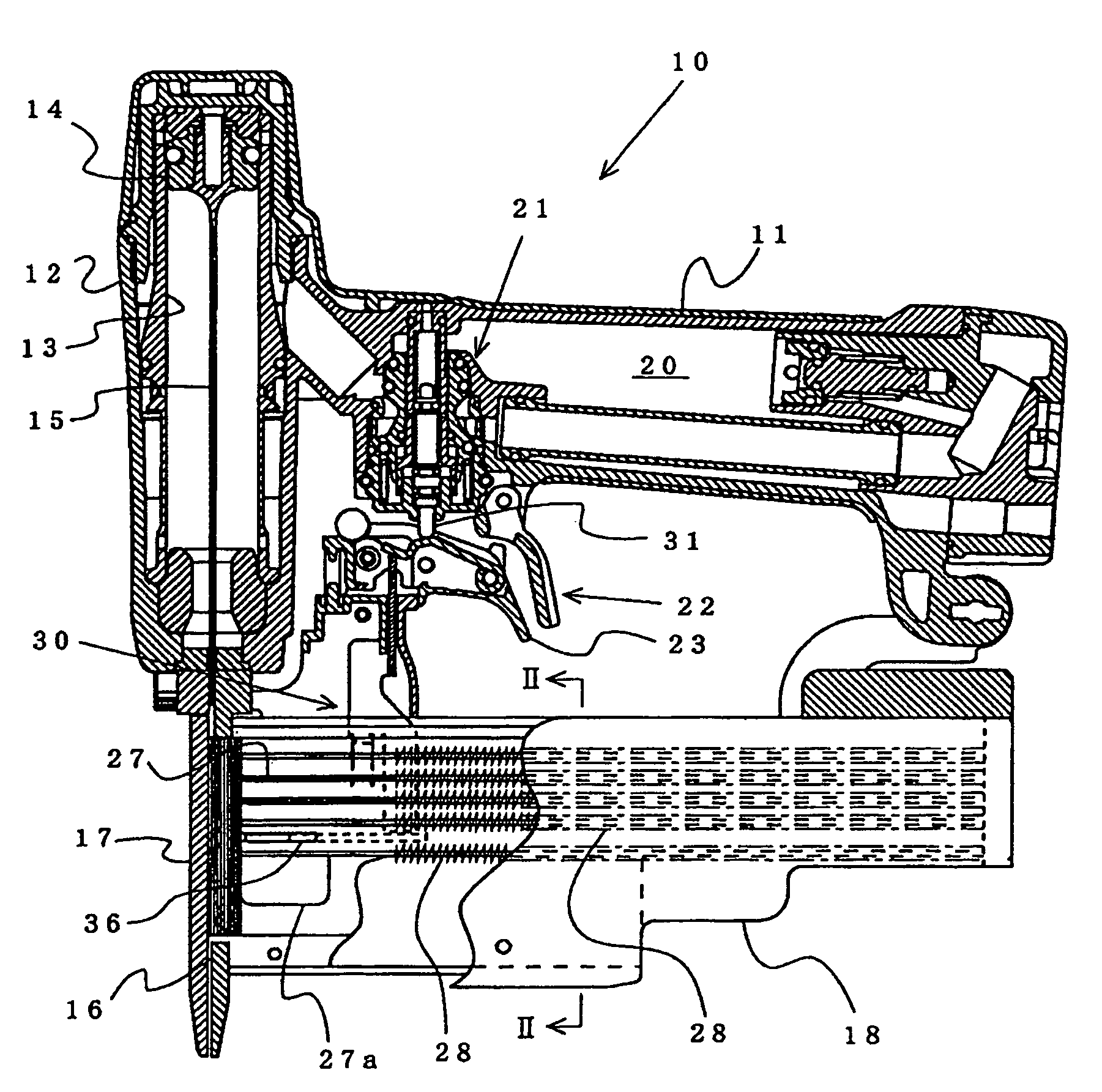
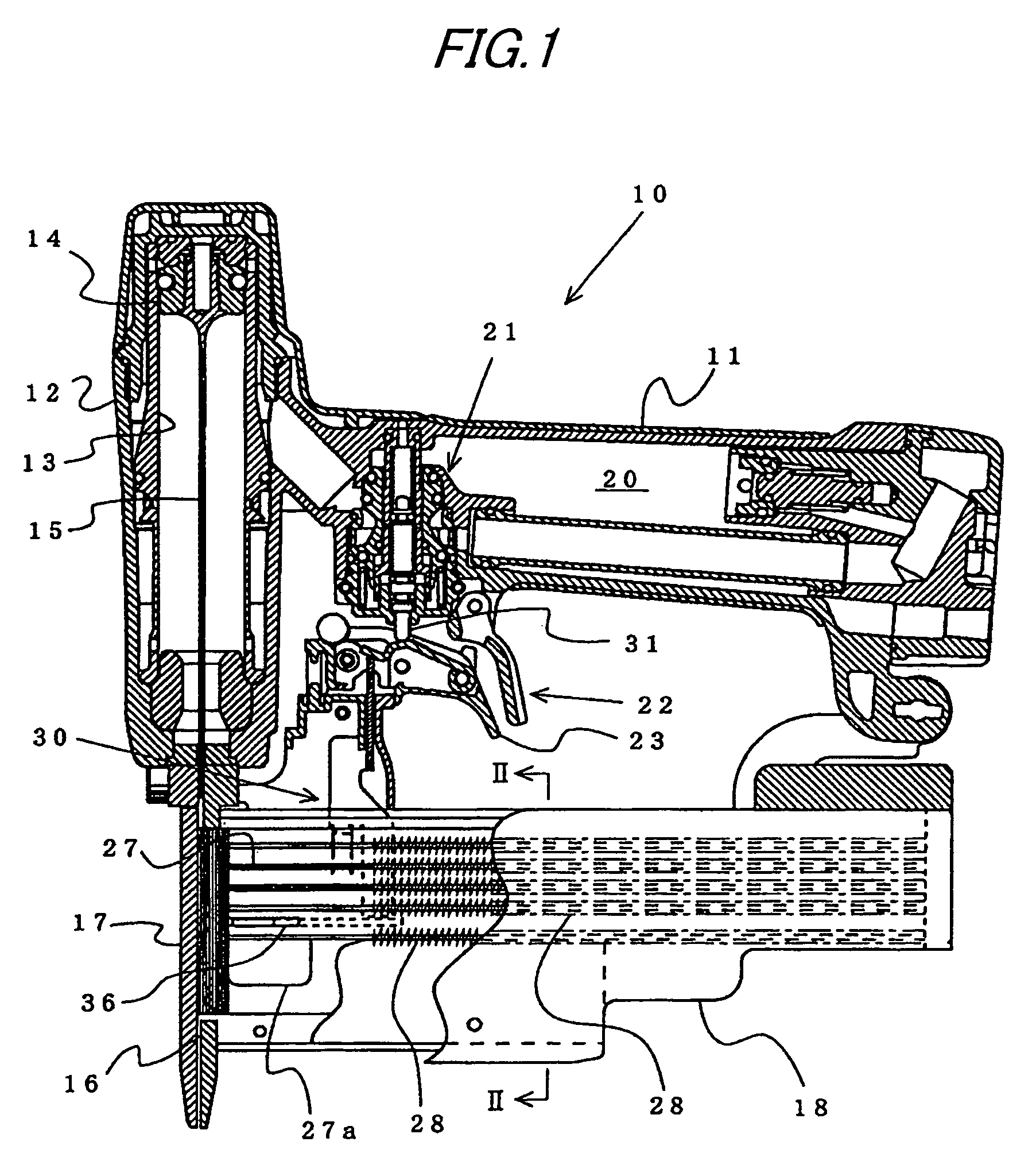
[0024]Embodiments of the present invention will be described with reference to the exemplary embodiments shown in the accompanying drawings. FIG. 1 shows the nailing machine 10 driven by compressed air according to an embodiment of the invention. Inside of a housing 12 in a hollow shape integrally formed with a grip portion 11 is contained with a drive mechanism constituted by a cylinder 13, a piston 14 contained at inside of the cylinder 13 and a driver 15 integrally coupled with the piston 14. A lower side of the housing 12 is attached with a nose portion 17 forming an injection port 16 for guiding to strike a nail. The driver 15 is contained in and guided by the injection port 16 formed at the nose portion 17. The magazine 18 containing connected nails is supported between the nose portion 17 and a rear end portion of the grip portion 11. Connected nails at inside of the magazine 18 are successively supplied into the injection port 16 of the nose portion 17. Further, by introduci...


PUM

PropertyMeasurementUnit
diameteraaaaaaaaaa
lengthaaaaaaaaaa
shapeaaaaaaaaaa

Abstract

A nailing machine includes a magazine for storing nails, an injection port, a drive mechanism, and a nail detecting lever. The nail detecting lever formed with a detecting end capable of advancing to inside of a nail containing portion is rotatably arranged between a downwardmost pusher and a pusher thereabove on one side of the magazine. An idle striking preventing arm has an upper end arranged at a vicinity of a starter, and a lower end arranged to be opposed to an end portion on a side opposed to a detecting end of the detecting lever and which is operated to start a nailing machine in cooperation with the starter. Further, the other side of the magazine is formed with a detecting end containing portion for containing the detecting end of the nail detecting lever.

Description

TECHNICAL FIELD[0001]The present invention relates to a nailing machine in which connected nails constituted by adhering contiguous nails by adhering or the like to connect are charged into a magazine in a shape of a straight sheath and successively pressed to supply into an injection port formed at a front end portion of the magazine, and the nail supplied into the injection port is continuously struck to a struck member by a drive mechanism driven impulsively. Particularly, the invention relates to an idle striking preventing mechanism of a nailing machine for preventing the nailing drive mechanism from being operated when there is not present the nail charged into the magazine.BACKGROUND ART[0002]In a background art, there is used a nailing machine in which connected nails connected by adhering contiguous nails in a state of aligning a number of nails in parallel are charged into a magazine, the connected nails at inside of the magazine are successively supplied into the injectio...

Claims


Application Information

Patent Timeline
13 Oct 2009
Publication
US7600661B2
IPC
B25C1/16; B25C7/00; B25C1/00; B25C1/04; B25C5/16
CPC
B25C5/1689; B25C1/005; B27F7/09; B25C7/00; B25C1/04
Inventors
ADACHI, MICHIAKI