Device and method for supplying short-wavelength light

a technology of short-wavelength light and device, which is applied in the direction of lasers, cosmonautic components, beacon systems, etc., can solve the problem of very limited transmission length, and achieve the effect of reducing the thermal influence of illumination devices and improving the service life of devices

Active Publication Date: 2009-10-13
LEICA MICROSYSTEMS CMS GMBH
View PDF3 Cites 0 Cited by
  • Summary
  • Abstract
  • Description
  • Claims
  • Application Information

AI Technical Summary

Benefits of technology

[0006]It is therefore the object of the present invention to propose a device for supplying short-wavelength light as well as a method for supplying short-wavelength light, in particular for the examination of specimens, the thermal influence of the illumination device being reduced and the service life of the device nevertheless being improved.
[0015]The device and the method according to the present invention for supplying short-wave light furthermore make it possible to arrange the heat-generating light source outside the climate-controlled chamber. At the same time, however, absorption of the light transmitted in the light guide is decreased, since longer light waves are now being transmitted therein and the losses in the fiber are therefore lower. Longer transmission distances can thus also be implemented, so that essentially more freedom exists in terms of arranging the illumination source relative to the measurement device.
[0016]With appropriate selection of a laser, not only the illumination source but also a first frequency multiplier, in particular, a frequency doubler, can be provided in the first subassembly, so that the wavelength generated in the laser is made smaller even before entering the optical waveguide. In this case a further frequency multiplier is additionally provided in the second subassembly, i.e., on the light exit side of the light guide, in the vicinity of the measurement point. A simpler design for the frequency multiplier in the vicinity of the measurement point is thus possible, so that space can be saved in this context.

Problems solved by technology

When short-wavelength light (at a wavelength shorter than 300 nm) is transmitted in a light guide, however, the relatively high absorptivity of the fiber means that the transmission length is very limited.

Method used


Image

  • Device and method for supplying short-wavelength light
  • Device and method for supplying short-wavelength light
  • Device and method for supplying short-wavelength light

Examples


Embodiment Construction

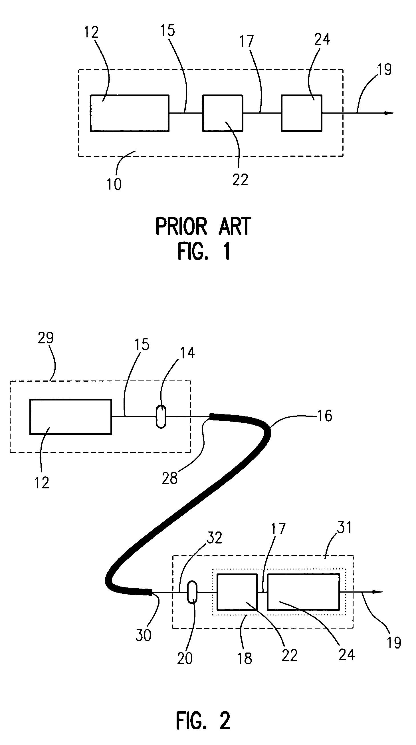
[0021]FIG. 1 shows a device 10 according to the existing art for supplying short-wavelength light.

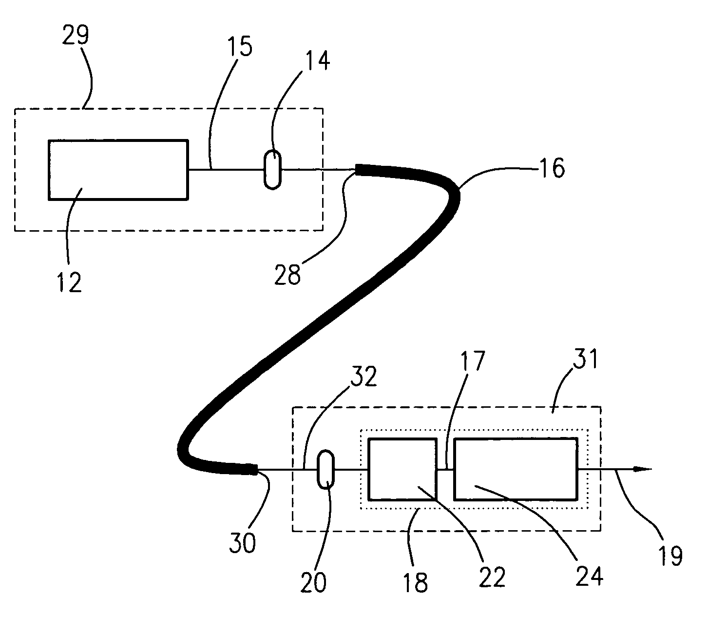
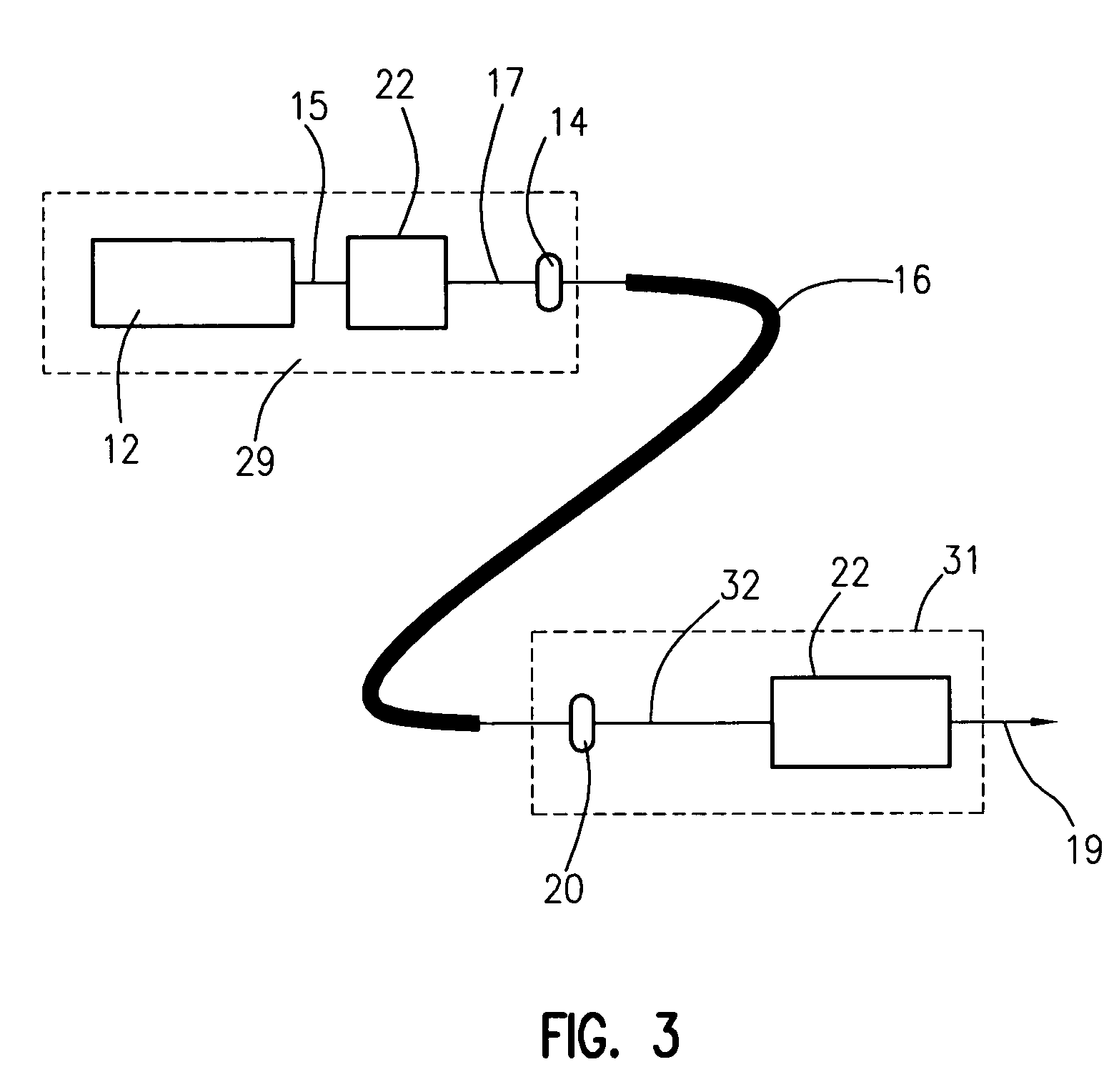
[0022]A device 10 comprises a light source 12 that is preferably constituted by a laser. A light beam 15 at a wavelength λ0 emerges from light source 12. Light beam 15 is conveyed, still inside device 10, to a frequency doubler 22. Inside device 10, a light beam 17 at a wavelength λ1, which typically corresponds to half of wavelength λ0, emerges from frequency doubler 22. Light beam 17 having wavelength λ1 can then be conveyed to a sum frequency mixer 24 as a second frequency multiplication stage. A light beam 19 at a wavelength λ2, whose frequency has likewise been multiplied with respect to wavelength λ1, then emerges from the second stage. The frequency multiplication in frequency doubler 22 or in sum frequency mixer 24 is based on nonlinear optical effects that occur in crystals at high light field strengths. In illumination devices10 known from the existing art, the entire assembla...


PUM


Abstract

The present invention broadly comprises a device for supplying light at an illumination wavelength shorter than 300 nm. The device includes a first subassembly, having a light source for delivering light at a wavelength that is at least twice as long as the illumination wavelength; a second subassembly having at least one means for wavelength reduction; and a light guide that guides the light from the light source of the first subassembly into the second subassembly. The present invention also broadly comprises a method for supplying light at an illumination wavelength shorter than 300 nm.

Description

CROSS REFERENCE TO RELATED APPLICATIONS[0001]This application claims priority of German patent application 10 2005 017 607.0, filed Apr. 16, 2005, which application is incorporated by reference herein.FIELD OF THE INVENTION[0002]The invention relates to a device for supplying short-wavelength light at an illumination wavelength shorter than 300 nm, and to a method for supplying short-wavelength light at an illumination wavelength shorter than 300 nm.BACKGROUND OF THE INVENTION[0003]Examination methods that require the use of electromagnetic waves, in particular short-wavelength light, are used in many ways in the examination of specimens. For example, it is necessary to inspect the results of producing a wafer, e.g., by inspecting layer thicknesses. A plurality of optical measurement arrangements, operating according to the principle of spectrophotometry or ellipsometry, are known from the existing art for the measurement of layer thicknesses. These arrangements allow both the layer...

Claims


Application Information

Patent Timeline
Patent Type & Authority Patents(United States)
IPC IPC(8): H01S3/30H01S3/10
CPCG02F1/37H01S3/005G03F7/70575
Inventor HEIDEN, MICHAEL
Owner LEICA MICROSYSTEMS CMS GMBH
Why Eureka
Try Eureka