Ultrasonograph, work flow edition system, and ultrasonograph control method

Inactive Publication Date: 2009-10-13
TOSHIBA MEDICAL SYST CORP
View PDF23 Cites 14 Cited by
  • Summary
  • Abstract
  • Description
  • Claims
  • Application Information

AI Technical Summary

Benefits of technology

[0011]The present invention has been made in view of the above circumstances, and has for its object to create a workflow protocol before an examination comparatively easily and promptly, in a workflow system wherein even a user

Problems solved by technology

There has been expected such an improper situation that the result of an examination differs depending upon the operating skill of the user, and the degradation of reliability attributed to the improper situation has been apprehended.
On the other hand, the ultrasonic diagnostic equipments have been introduced, not only in large hospitals, but also in many hospitals, with the per

Method used


Image

  • Ultrasonograph, work flow edition system, and ultrasonograph control method
  • Ultrasonograph, work flow edition system, and ultrasonograph control method
  • Ultrasonograph, work flow edition system, and ultrasonograph control method

Examples


Embodiment Construction

[0060]Now, an ultrasonic diagnostic equipment, a workflow editing system, and a method of controlling the ultrasonic diagnostic equipment, according to one embodiment of the present invention, will be concretely described with reference to the accompanying drawings.

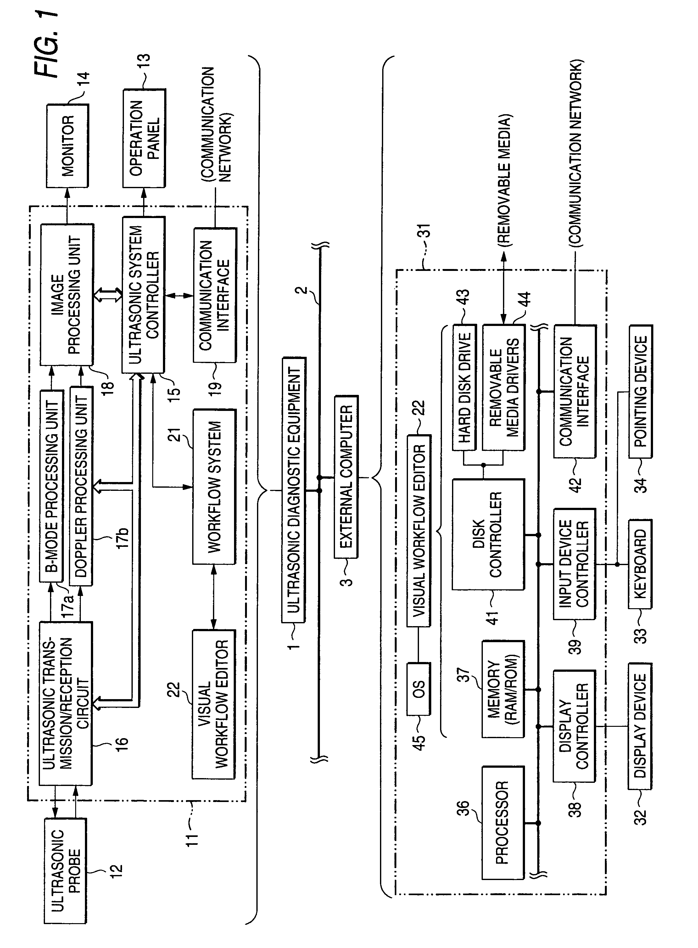
[0061]FIG. 1 shows the outline of a medical image diagnosis system which comprises the ultrasonic diagnostic equipment 1 according to this embodiment, and an external computer 3 that is communicably connected to the ultrasonic diagnostic equipment 1 through a communication network (hereinbelow, simply termed “network”) 2 such as LAN (local area network) The network 2 here includes, not only a LAN in facilities such as a hospital, but also a wide-area computer network such as the Internet, which is available in conformity with a predetermined communication protocol (such as TCP / IP) through a communication network (including also a radio channel) such as dedicated line or public network.

[0062]In the medical image diagnosis ...


PUM


Abstract

The present invention relates to an ultrasonic diagnostic equipment 1 which projects ultrasonic signals into a patient, and which generates an ultrasonic image on the basis of reflection echoes from within the patient. The ultrasonic diagnostic equipment 1 comprises a workflow system 21 which controls equipment operations including the generation of the ultrasonic image, in accordance with a workflow protocol based on the examination procedure of steps created beforehand, and a visual workflow editor 22 which is so constructed as to edit the workflow protocol visually with icons on a screen. Owing to the configuration, the creation of the workflow protocol is facilitated, chances for the utilization of the workflow system are expanded, and even users, such as beginners, who are slightly skilled in the ultrasonic diagnostic equipment and have experienced operations little, are permitted to master the operating method of the equipment promptly and to operate the equipment more easily.

Description

TECHNICAL FIELD[0001]The present invention relates to an ultrasonic diagnostic equipment which depicts the state of the internal organ or blood flow of a patient by using ultrasonic waves, so as to examine and diagnose the internal organ or blood flow, a workflow system (also called “IASSIT: Intelligent Assistant System”) in which, before the examination with the ultrasonic diagnostic equipment, a workflow expressing the procedure of the examination is defined as one (also called “workflow protocol”) consisting of a plurality of items to-be-performed (also called “functional units” or “activities”) executable by the ultrasonic diagnostic equipment, so as to control the operation of the ultrasonic diagnostic equipment in accordance with the workflow protocol during the examination, and a workflow editing system which serves to visually edit and create the workflow protocol for the workflow system, on the screen of the ultrasonic diagnostic equipment or an external computer.BACKGROUND...

Claims


Application Information

Patent Timeline
IPC IPC(8): G05B11/01A61B8/00A61B8/06
CPCA61B8/00G01S7/52098A61B8/12A61B8/06
Inventor SANO, AKIHIROKAMIYAMA, NAOHISAOGASAWARA, YOICHI
Owner TOSHIBA MEDICAL SYST CORP
Why Eureka
Try Eureka