System and method for providing image forming composition on a substrate using a drop on demand ink printer

a technology of drop on demand and image forming composition, which is applied in the direction of dyeing process, printing, textiles and paper, etc., can solve the problems of preventing nozzle depriming problems, difficult and time-consuming use of a plurality of different strands, and reducing the uniformity of printing ink to the individual, so as to achieve high viscosity inks and prevent nozzle depriming problems

Inactive Publication Date: 2009-10-20
WILLETT INT
View PDF9 Cites 21 Cited by
  • Summary
  • Abstract
  • Description
  • Claims
  • Application Information

AI Technical Summary

Benefits of technology

[0015]Accordingly, the present invention provides a method for applying an image forming composition to one or more sides of a mesh fabric using a drop on demand ink printer, characterised in that the printer is operated at a fluid pressure of between 1 and 3.5 bar. Preferably the image forming composition has a viscosity of less than 100 cp and further preferably the image forming composition viscosity is in the range of 5 to 20 cp. The use of a pressurised fluid provides significant advantage in textile printing when compared with the more commonly utilised in impulse jet systems. Variable positive pressure provides the ability to jet higher viscosity inks such as that typically used in textile printing and prevents nozzle depriming problems often suffered by impulse jet products.
[0016]A particularly preferred drop on demand ink jet printer is one having an array of nozzles in which a solenoid valve controls the flow of an ink through the individual nozzle orifices and the nozzle orifices have a diameter of from 20 to 200 μm, notably about 40 to 60 μm for thin mesh fabric types. and in which the plunger of the solenoid valve has a diameter of less than 2.5 mms. Such valves can be constructed so as to be compact and thus capable of printing closely separated dots and in which the formation of the drops at the nozzle orifices is accurately controlled, thus further enhancing the definition of the printed image. We have also found that the use of such a printer enables individual control of the printing of the dots of the image so that accurate over-printing of dots or dosing strips can be achieved, thus enhancing the colour range and strength which can be achieved. Such a printer thus enables an infinite scaling of the colour hues which can be achieved.

Problems solved by technology

However, this is difficult and time consuming, especially where the pattern is complex and / or a plurality of colours or textures are desired.
Such use of a plurality of different strands is becoming progressively uneconomic in the large scale manufacture of commodity materials, such as patterned carpets.
However, problems arise in securing even application of the printing ink to the individual strands or fibres of the pile.
(as is commonly used in an ink jet printer) is used, it will run down the length of the strands and form an intense coloration at the base of the pile, leaving the top portion of the pile inadequately dyed, and little penetration of the colour into the strands will take place.
Such viscous inks are difficult to jet through the very fine orifice nozzles, typically less than 500 micrometer diameter, and pressures far in access of those for which a valve ink jet printer is normally designed would be required.
Furthermore, if a low viscosity ink were applied at such high pressures, it may issue from the nozzles as high powered jets and cause the individual strands to bend over and thus prevent the ink from contacting other strands in the pile.
Whilst the use of large diameter nozzles for high viscosity inks enables the ink to be deposited on the strands of the pile to achieve substantially uniform coloration of the individual strands and fibres, the size of the droplets issuing from the nozzle are sufficiently large to cause perceptible loss of definition in the printed pattern.
Furthermore, the size of the droplets can result in adjacent droplets applied to the pile contacting one another to cause colour bleeding where the droplets are of different colours.
This tends to result in pale colours being printed unless multiple print passes are used which significantly slows down the linear print rate.
The other disadvantages associated with impulse jet printing technologies include the low pressures at which impulse jet printers operate and the low viscosity inks that must be used with the printers.
This is a particular disadvantage for textile printing as higher viscosity inks are preferred as they provide a more consistent depth of colour pick up through the textile, which is vital to obtaining quality print.
Impulse jet heads do not have the capability for higher viscosity inks or high pressure application.

Method used


Image

  • System and method for providing image forming composition on a substrate using a drop on demand ink printer
  • System and method for providing image forming composition on a substrate using a drop on demand ink printer
  • System and method for providing image forming composition on a substrate using a drop on demand ink printer

Examples


Embodiment Construction

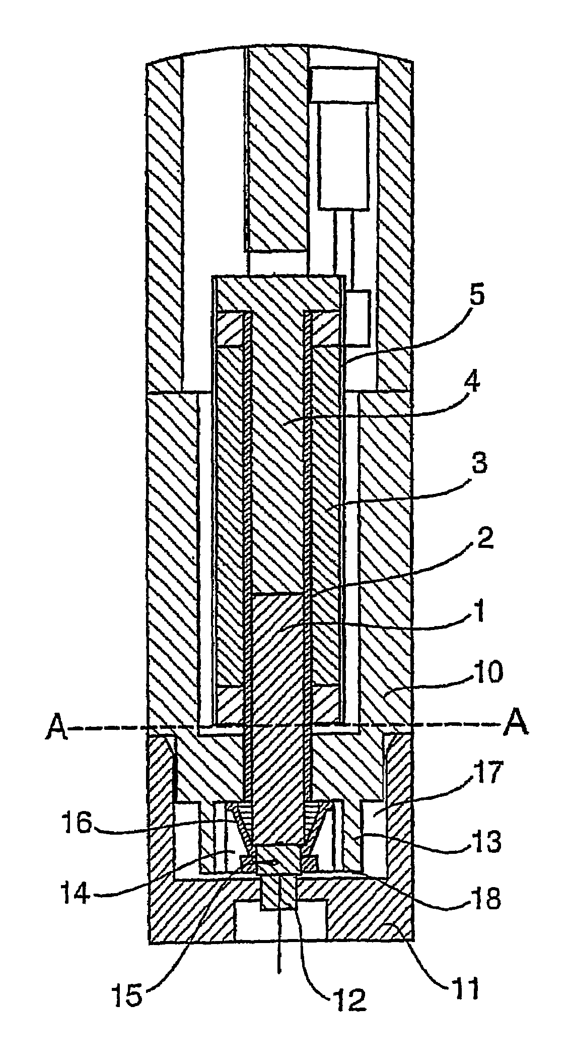
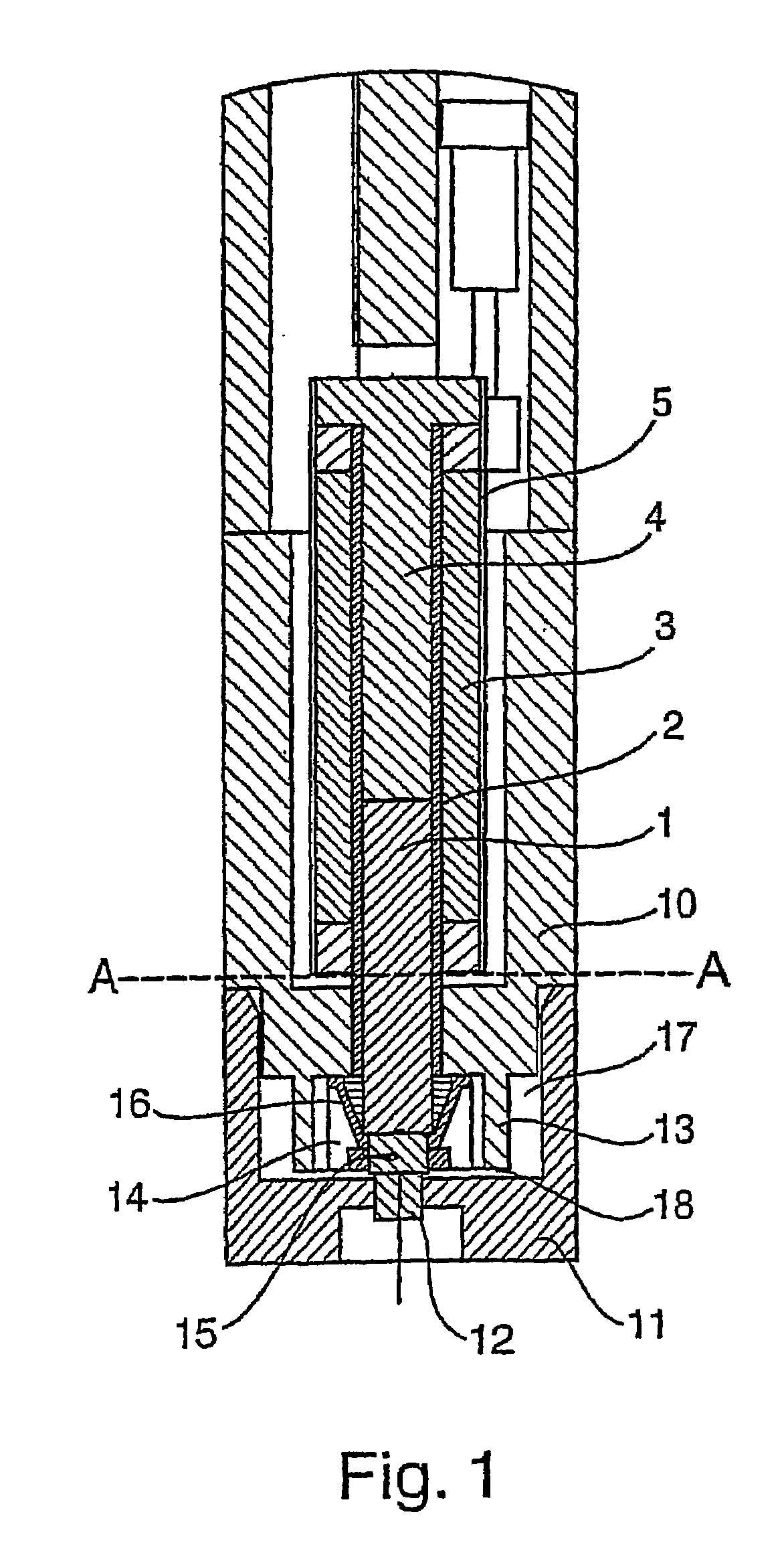
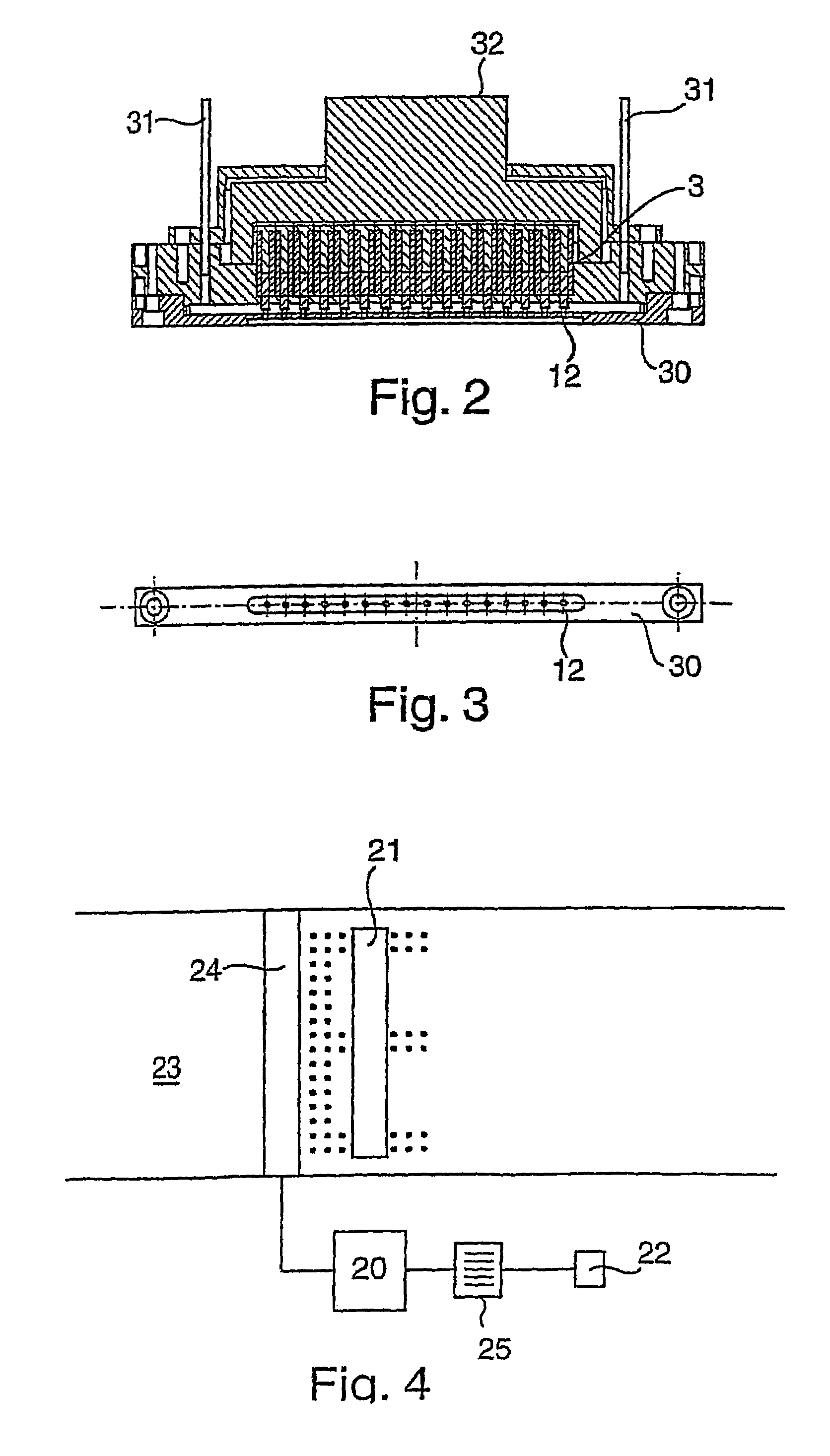
[0059]The valve of FIG. 1 comprises a plunger 1 which is journalled as a close, free sliding fit for axial reciprocation in a stainless steel tube 2. Tube 2 has a thin insulating coating or sleeve (not shown) formed upon its outer face and supports a coil 3 wound upon it. Coil 3 is supplied with an electric current from a source (not shown) under the control of a computer 20, shown in FIG. 4. A stop 4 is mounted at the proximal end of tube 2 to limit the axial retraction of plunger 1 within tube 2. The coil 3 is encased in a metal cylindrical housing 5.

[0060]The above assembly is mounted in a support housing 10 which extends axially beyond the distal end of the coil and has a transverse end wall 11 which carries a jewel nozzle 12. In the embodiment shown in FIG. 1, housing 10 has an axially extending internal annular wall 13 which forms the radial wall of the valve head chamber 14 into which the distal end of the plunger extends. The distal end of the plunger 1 carries a terminal ru...


PUM

PropertyMeasurementUnit
diameteraaaaaaaaaa
coercivityaaaaaaaaaa
saturation flux densityaaaaaaaaaa

Abstract

A method of printing onto one or more sides of a mesh fabric, such a polyester mesh typically used for flags and banners, using a drop on demand ink printer, wherein the printer is operated at a fluid pressure of between 1 and 3.5 bar and that the image forming composition has a viscosity of less than 100 cp.

Description

[0001]The present invention relates to a method, notably to a method for printing images onto fibrous materials.BACKGROUND TO THE INVENTION[0002]Many fabrics, both woven, looped and non-woven, have a surface which presents free ends of fibres generally normal to the plane of the fabric. Such fabrics include felted materials where fibres in a randomly orientated mass are compressed, optionally in the presence of a bonding agent such as an adhesive; materials woven from strands made up from a plurality of individual fibres where the surface of the fabric has been, brushed, teased, abraded or otherwise treated to separate some of the fibres from within the strands to form a fluffy surface to the material, for example a brushed nylon; woven materials made from materials which are inherently fluffy, such as knitted or woven angora, merino or cashmere wools or cotton terry towelling; and carpet type materials such as velvets, velours and tufted carpets where individual lengths of strands ...

Claims


Application Information

Patent Timeline
Patent Type & Authority Patents(United States)
IPC IPC(8): B41J2/04B41J3/407D06P5/30
CPCB41J3/4078D06P5/30B41J2202/05B41J2002/041
Inventor HORSNELL, DAVID ANDREWTOMLIN, MATTHEW BRIANLECHEHEB, AMMARPRIME, OLIVER JOHNFOX, MICHAEL JAMESBATES, CHRISTOPHER MICHAEL
Owner WILLETT INT
Why Eureka
Try Eureka